Synchronous assembly

A technology of synchronous components and synchronous rings, applied in clutches, mechanical drive clutches, mechanical equipment, etc., can solve problems such as vibration and uneven operation of three-cylinder engines, and achieve high rigidity

Active Publication Date: 2015-11-25
HOERBIGER ANTRIEBSTECHN HLDG
View PDF5 Cites 8 Cited by
  • Summary
  • Abstract
  • Description
  • Claims
  • Application Information

AI Technical Summary

Problems solved by technology

Such vibrations lead to internal loading of the synchronizer ring itself and can also lead to uncontrolled impact of the synchronizer ring on the components surrounding it in the transmission, and in this case further vibrations can be caused
In addition, vibrations can be caused by uneven running of the drive shaft, which will be amplified by the tendency for internal combustion engines used in motor vehicles to have fewer and fewer cylinders; three-cylinder engines run more unevenly than four-cylinder engines

Method used


Image

  • Synchronous assembly
  • Synchronous assembly
  • Synchronous assembly

Examples


Embodiment Construction

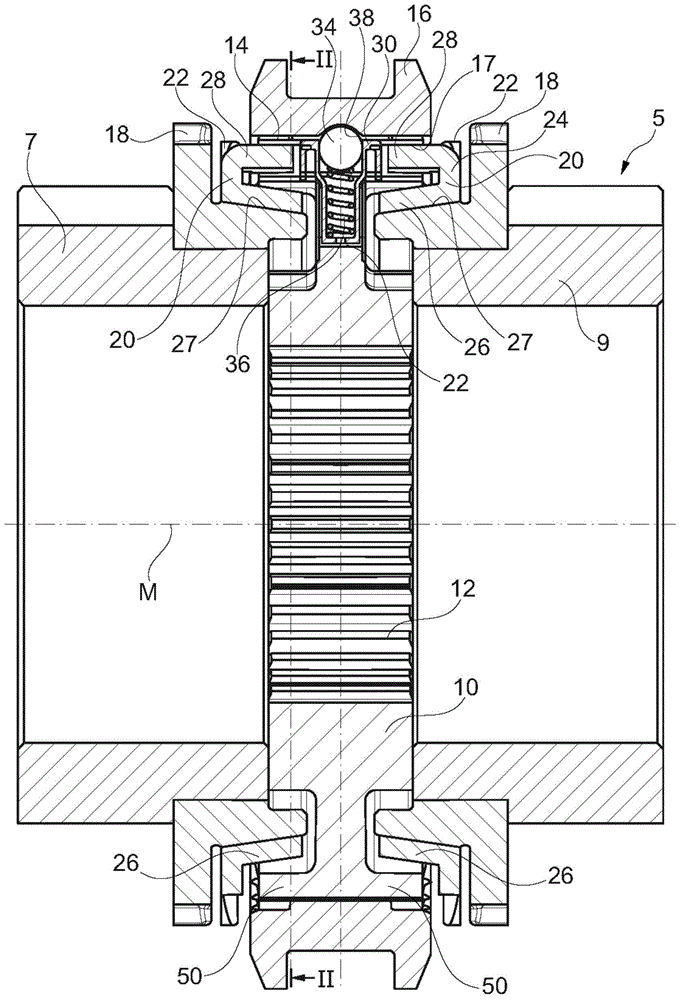
[0021] exist figure 1 A synchronization assembly 5 according to a first embodiment is shown in , which is used to connect the two drive gears 7 , 9 , shown schematically here, in a rotationally fixed manner to a drive shaft (not shown). Here, for the sake of simplicity, the transmission gears 7 , 9 are shown with the same diameter; in practice they have different diameters. It is of course also possible to assign only a single gear and thus a single transmission gear to the synchronization assembly.

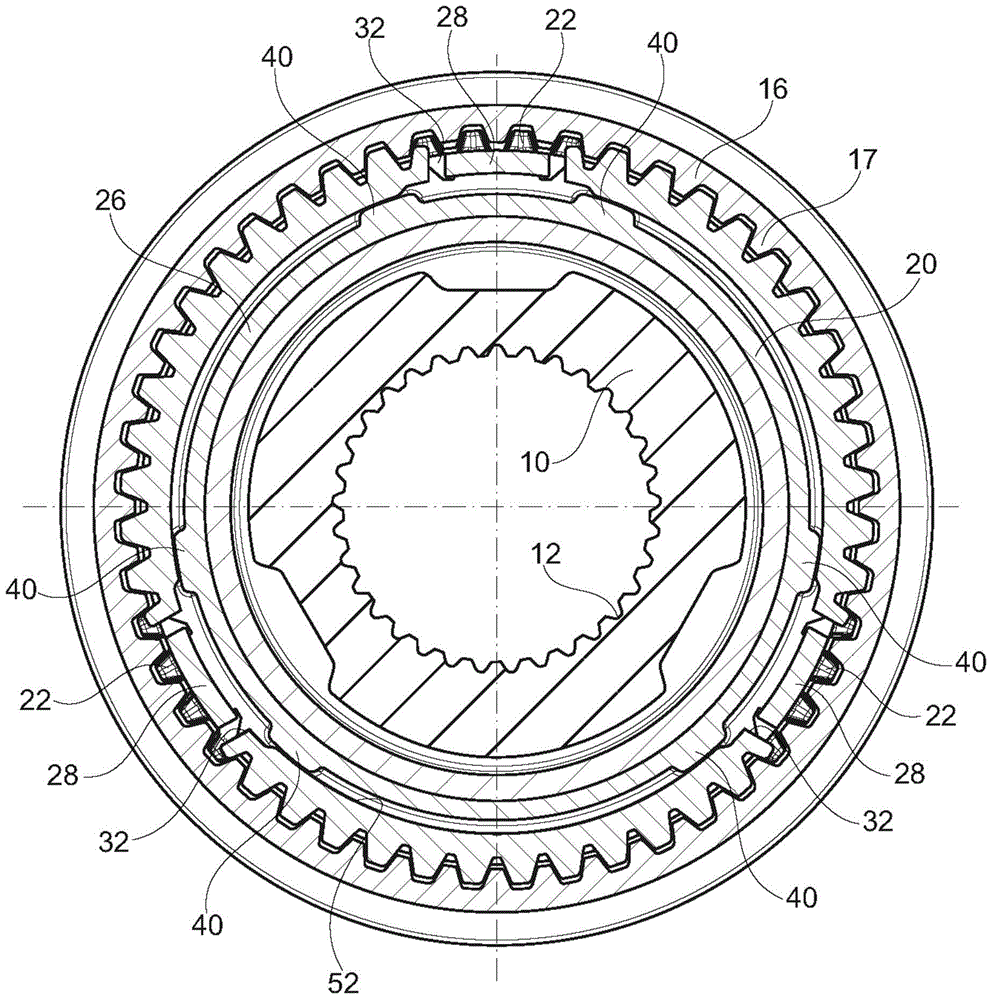
[0022] The synchronizing unit 5 comprises a hub 10 (also referred to as synchronizing body), which is arranged on the drive shaft in a rotationally fixed manner by means of a hub toothing 12 . The drive shaft extends along a center axis M which is at the same time the center axis and the axis of rotation for the drive gears 7 , 9 and the synchronizing assembly 5 .

[0023] The drive gears 7 , 9 are arranged on the drive shaft as idler gears. When one of the gears is to be use...


PUM


Abstract

The invention relates to a synchronizer assembly having a hub, at least one pressure piece which is mounted on the hub, and at least one synchronous ring which is provided with a friction body and a locking flange, wherein the friction member of the synchronizer ring is provided with a plurality of starting up, the starting up extending from the locking flange and adapted to cooperate with the hub.

Description

technical field [0001] The invention relates to a synchronizing assembly having a hub, at least one pressure part and at least one synchronizing ring. The invention relates in particular to such a synchronization assembly, which is used in a synchronization system of the "BorgWarner" type. Background technique [0002] In a BorgWarner synchronization system, a hub (also referred to as a synchronization body) is arranged in a rotationally fixed manner on a shaft of a transmission, which is used, for example, in motor vehicles. Arranged on the hub in a rotationally fixed manner, but displaceable in the axial direction, is a sliding sleeve for producing a rotationally fixed connection with a drive gear mounted rotatably on both sides of the hub on the drive shaft . For this purpose, the gear is provided with a shift toothing, onto which the edge section of the sliding sleeve can be pushed. [0003] Before the sliding sleeve engages in the switching toothing, the rotational s...

Claims


Application Information

Patent Timeline
Patent Type & Authority Applications(China)
IPC IPC(8): F16D23/06
CPCF16D23/025F16D23/06F16D2023/0618
Inventor C·韦伊尔B·奈格勒M·肖儿
Owner HOERBIGER ANTRIEBSTECHN HLDG
Why Eureka
Try Eureka