Multi-path rotating joint

A rotary joint, multi-channel technology, applied in the direction of pipe components, etc., can solve the problems of low production efficiency, waste of material resources, easy wear of seals, etc., and achieve the effect of stable rotation

Inactive Publication Date: 2015-11-25
TENGZHOU TIANXUAN ROTARY UNION
View PDF3 Cites 1 Cited by
  • Summary
  • Abstract
  • Description
  • Claims
  • Application Information

AI Technical Summary

Problems solved by technology

The production efficiency of the ordinary rotating device currently used is low, and the unbalanced sealing structure is basically adopted. The seal is easy to wear, has a short service life, frequent replacement, and wastes material and financial resources.

Method used


Image

  • Multi-path rotating joint
  • Multi-path rotating joint

Examples


Embodiment Construction

[0009] Below in conjunction with accompanying drawing, the present invention will be further described:

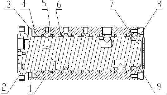
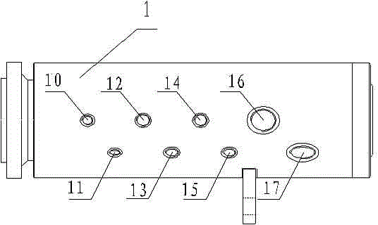
[0010] like figure 1 , figure 2 As shown, a multi-channel rotary joint includes a housing 1, an outer tube 2, a retaining ring 3 for holes, a first ball bearing 4, a seal 5, a first combination seal ring 6, a second ball bearing 7, and an end cover 8. The second combination retaining ring 9 is characterized in that: the two ends of the shell 1 and the outer tube 2 are supported by two ball bearings, the first ball bearing 4 and the second ball bearing 7, and the first ball bearing 4 and the second ball bearing Between the two ball bearings 7, there are seals 5 and a first combination seal ring 6 in sequence; two of the seals 5 are low-pressure seals, and seven first combination seal rings 6, the casing 1 and the outer The tube 2 is divided into 8 sealing areas. In the sealing area, the housing 1 and the outer tube 2 are respectively designed with a first passage 10, a s...


PUM


Abstract

The invention discloses a multi-path rotating joint which comprises a casing, outer tubes, retaining rings for holes, first ball bearings, sealing elements, first combined sealing rings, second ball bearings, end covers and second combined retaining rings. The multi-path rotating joint is characterized in that the first ball bearings and the second ball bearings are arranged at two ends of the casing and the outer tubes for supporting; the sealing elements and the first combined sealing rings are sequentially arranged between the first ball bearings and the second ball bearings; the sealing elements are two low-pressure sealing elements; the number of the first combined sealing rings is seven; the casing and the outer tubes are segmented into eight sealing areas; a first path, a second path, a third path, a fourth path,, a fifth path, a sixth path, a seventh path and an eighth path are respectively arranged on the casing and the outer tubes in the sealing areas; the end covers and the second combined retaining rings are arranged at one end of the rotating joint; the retaining rings for the holes are arranged at the other end of the rotating joint. The multi-path rotating joint can allow multiple mediums to simultaneously flow through and can also bear a great pressure difference among the paths.

Description

technical field [0001] The invention belongs to a rotary joint, in particular to a multi-channel rotary joint. Background technique [0002] In metallurgy, iron and steel, engineering machinery, drilling and other industries, it is often encountered that there are multiple media of liquid and gas between the fixed parts and the rotating machine that need to be transmitted at the same time, and there is a large pressure difference between the channels, and the installation space is limited. question. Basically, it is solved by adopting a plurality of ordinary rotating devices with a small pressure difference through a single medium. The production efficiency of the ordinary rotary devices currently used is low, and they basically adopt an unbalanced sealing structure. The seals are easy to wear, have a short life, and are frequently replaced, which wastes material and financial resources. Contents of the invention [0003] Aiming at the deficiencies of the above-mentioned...

Claims


Application Information

Patent Timeline
Patent Type & Authority Applications(China)
IPC IPC(8): F16L39/06
CPCF16L39/06
Inventor 盖延峰邵明秋郭峰
Owner TENGZHOU TIANXUAN ROTARY UNION
Why Eureka
Try Eureka