
Cam shaft phase sensor test method

A technology of phase sensor and testing method, which is applied in the direction of instruments, etc., can solve the problems of the influence of the detection accuracy of the axle phase sensor function, the high requirements of the operator, and the influence of the detection efficiency, so as to achieve high test efficiency, good test accuracy, and reduce detection cost effect

Active Publication Date: 2015-11-25
ANHUI RIZEN AUTO PARTS
View PDF6 Cites 1 Cited by
  • Summary
  • Abstract
  • Description
  • Claims
  • Application Information

AI Technical Summary

Problems solved by technology

In this test method, the operator needs to be able to accurately judge whether the display parameters of the oscilloscope meet the requirements, which has high requirements for the operator. At the same time, relying on the operator's artificial judgment, the accuracy of the wheel axle phase sensor function detection is affected, and the detection efficiency is also affected.

Method used


Image

  • Cam shaft phase sensor test method

Examples


Embodiment Construction

[0022] The specific implementation manner of the present invention will be described in further detail below by describing the best embodiment with reference to the accompanying drawings.

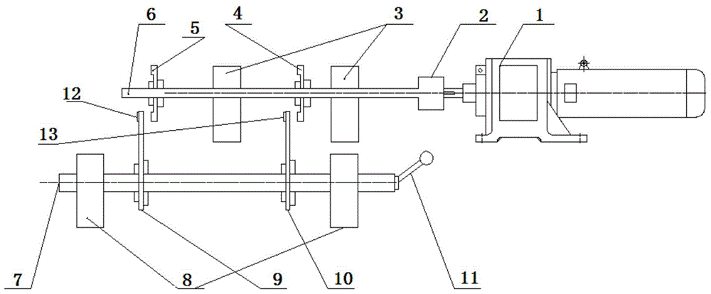
[0023] refer to figure 1 , the test method of camshaft phase sensor, specifically:

[0024] Install the first signal target wheel 5 and the second signal target wheel 4 with the same structure on the rotating shaft 6 connected with the motor 1;

[0025] Standard sample fixed cantilever 9 and test sample fixed cantilever 10 are installed on the fixed shaft 7, the sensor standard part 12 of testing first signal target wheel 5 rotation phase is installed on the standard sample fixed cantilever 9, and the test sample is fixed on the cantilever 10 A sensor test piece 13 for testing the rotational phase of the second signal target wheel 4 is installed;

[0026] The distance between the sensor standard part 12 and the first signal target wheel 5 is equal to the distance between the standard samp...


PUM


Abstract

The invention discloses a cam shaft phase sensor test method. A rotation shaft connected with a motor is equipped with a first signal target wheel and a second signal target wheel; a fixation shaft is equipped with a standard sample member fixation cantilever and a test sample member fixation cantilever; the standard sample member fixation cantilever is equipped with a sensor standard member for testing the rotation phase of the first signal target wheel; the test sample member fixation cantilever is equipped with a sensor detection member for testing the rotation phase of the second signal target wheel; the sensor standard member and the sensor detection member are connected with an oscilloscope; the motor drives the rotation shaft to rotate, and the first signal target wheel and the second signal target wheel are in synchronous rotation; the rotation phase of the first signal target wheel and the waveform of the standard sample member are displayed through the oscilloscope; the rotation phase of the second signal target wheel and the waveform of the test member are displayed through the oscilloscope; and by comparing the waveform of the standard sample member and the waveform of the test member, the performance of the cam shaft phase sensor test member is judged. The cam shaft phase sensor test method is visual in judgment, high in test efficiency and good in test precision.

Description

technical field [0001] The invention relates to a camshaft phase sensor detection technology, in particular to a camshaft phase sensor testing method. Background technique [0002] After the production of the camshaft phase sensor is completed, performance testing is required to maintain the consistency of the product's ex-factory quality. In the prior art, the function detection of the camshaft phase sensor is realized by directly testing the output signal of the camshaft phase sensor with an oscilloscope, and judging by displaying parameters of the oscilloscope. In this test method, the operator needs to be able to accurately judge whether the oscilloscope display parameters meet the requirements, which has high requirements for the operator. At the same time, relying on the operator's artificial judgment, the accuracy of the wheel axle phase sensor function detection is affected, and the detection efficiency is also affected. Contents of the invention [0003] The purp...

Claims


Application Information

Patent Timeline
IPC IPC(8): G01D18/00
Inventor 李军涛
Owner ANHUI RIZEN AUTO PARTS
Learn More