
Fixed-point collection device for rubidium filled in rubidium bulbs

A collection device and rubidium amount technology, applied in the aerospace field, can solve the problems of difficult control of rubidium bubble quality, large deviation of rubidium amount, waste of raw materials, etc., and achieve the effects of saving precious raw materials, easy control of contact force, and convenient accurate measurement.

Inactive Publication Date: 2015-11-25
权富成
View PDF4 Cites 0 Cited by
  • Summary
  • Abstract
  • Description
  • Claims
  • Application Information

AI Technical Summary

Problems solved by technology

[0004] The existing rubidium bubble manufacturing process is subject to the limitations of technology and equipment. The amount of rubidium filled in the rubidium bubble is driven by the flame of the lampworker. The subjective judgment of the sensory perception results in a large deviation in the amount of rubidium, and the quality of the rubidium bubble is difficult to control. Increased the difficulty of subsequent debugging and testing, the pass rate was about 12%, resulting in a large waste of rubidium raw materials, especially the isotopes rubidium 87 and rubidium 85 (unit price of rubidium 87 isotope: 190,000 yuan / g)
At the same time, the rubidium bubble is stored at room temperature after vacuum filling, and is discretely bonded to the inner wall of the bubble in the form of solid powder. The measurement method is measured by DSC differential scanning calorimetry, and the integrity of the scan is blocked by the clamping part, so the rubidium cannot be accurately measured. Quantity, there is no standard quantity reference for lamp workers charging rubidium
Therefore, in order to obtain a rubidium bubble with a suitable amount of rubidium, it is necessary to repeat a large number of productions and undergo multiple screenings, which will easily cause serious waste of raw materials.

Method used


Image

  • Fixed-point collection device for rubidium filled in rubidium bulbs

Examples


Embodiment Construction

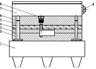
[0022] Such as figure 1 As shown, the rubidium bubble is filled with a fixed-point collection device for rubidium, which includes a heating device 1 and a metal cavity placed on the heating device 1, a refrigerant circulation box 7 and a cooling body 5.

[0023] The metal mold cavity is composed of a lower cavity 2 and an upper cavity 3 with built-in rubidium bubbles connected together. The bottom of the lower cavity 2 is connected to the heating device 1; the top of the upper cavity 3 is provided with a heat insulation layer 4. A cooling body 5 is provided on the heat insulation layer 4; a cooling body core assembly 8 is provided on the upper part of the cooling body 5, and the cooling body core assembly 8 is connected with the refrigerant circulation box 7; the cooling body core assembly 8 passes through the heat insulation layer 4 is in contact with the rubidium bubble; the two ends of the bottom of the lower cavity 2 are respectively provided with a guide column 6 which pa...


PUM

PropertyMeasurementUnit
thermal conductivityaaaaaaaaaa
thicknessaaaaaaaaaa
melting pointaaaaaaaaaa

Abstract

The invention relates to a fixed-point collection device for rubidium filled in rubidium bulbs. The device comprises a heating device as well as a metal cavity, a refrigerant circulation box and a cooling body which are placed on the heating device, wherein the metal cavity comprises a lower cavity and an upper cavity which are connected and internally provided with the rubidium bulbs, and the bottom of the lower cavity is connected with the heating device; a thermal insulating layer is arranged at the top of the upper cavity, and the cooling body is arranged on the thermal insulating layer; a cooling body core component is arranged at the upper part of the cooling body, connected with the refrigerant circulation box, and contacted with the rubidium bulbs through the thermal insulating layer; and guide columns penetrating through the upper cavity, the thermal insulating layer and the cooling body sequentially are symmetrically arranged at two ends of each bottom corner of the lower cavity respectively. The fixed-point collection device rubidium filled in rubidium bulbs achieves accurate measurement and improves the production efficiency effectively.

Description

technical field [0001] The invention relates to the field of aerospace technology, in particular to a fixed-point collection device for rubidium quantity filled in a rubidium bubble. Background technique [0002] Rubidium is a silver-white rare alkali metal with a density of 1.532 g / cm3, a melting point of 38.89°C and a boiling point of 688°C. The chemical properties of rubidium are extremely active, and it can spontaneously ignite at room temperature and in the air. Rubidium can also react violently when it comes into contact with water or even ice at a temperature as low as -100°C. Under the action of light, rubidium is easy to release electrons. Due to the high activity of rubidium, it must be placed in a device that is tightly isolated from the air during production, use, storage and transportation. Usually preserved in liquid paraffin. [0003] The wall thickness of the vacuum glass bubble is 0.4mm, and the shape is mostly spherical or cylindrical. In a clean vacuum s...

Claims


Application Information

Patent Timeline
Patent Type & Authority Applications(China)
IPC IPC(8): G01N1/10G01N25/20
Inventor 权富成高炳天冯浩
Owner 权富成
Learn More