Balance wheel with hairspring, speed regulator, movement, and clock
A technology of hairspring balance wheel and governor, which is applied in the fields of governor, hairspring balance wheel, movement and clocks and watches to achieve the effects of excellent durability, thinning and preventing damage
- Summary
- Abstract
- Description
- Claims
- Application Information
AI Technical Summary
Problems solved by technology
Method used
Image

Examples
no. 1 approach
[0040] Hereinafter, a first embodiment of the present invention will be described using the drawings.
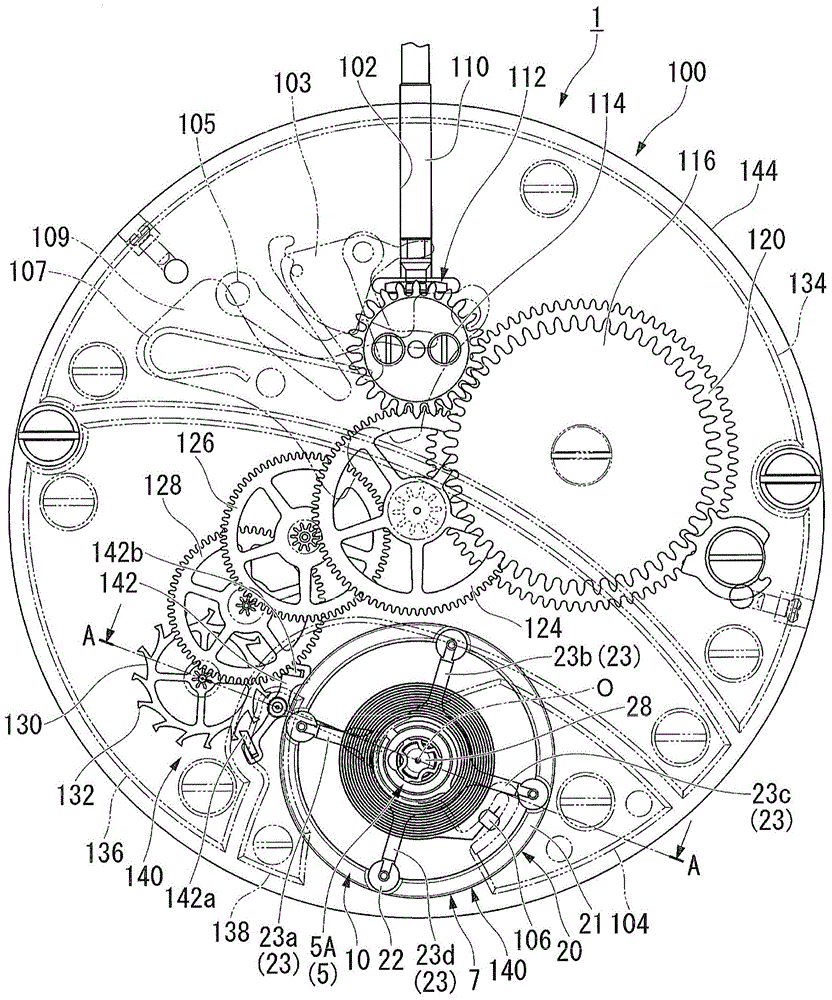
[0041] Hereinafter, a mechanical watch (equivalent to the "watch" in the claims, hereinafter simply referred to as "watch") and the movement incorporated in the watch will be described, and then the balance with hairspring and the governor constituting the movement will be described. Detailed description.
[0042] (clock)
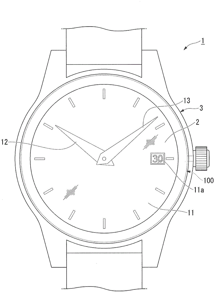
[0043] Generally, a mechanical body including a driving part of a timepiece is called a "movement". The dial and the hands are attached to the movement and placed in the watch case to form a finished product. The above state is called "complete" of the watch. Of the two sides of the bottom plate constituting the base plate of the timepiece, the side where the glass of the timepiece case is located, that is, the side where the dial is located is referred to as the "back side" of the movement. And, among the two sides of the bottom plate, the side where ...
no. 2 approach
[0114] Next, a second embodiment will be described.
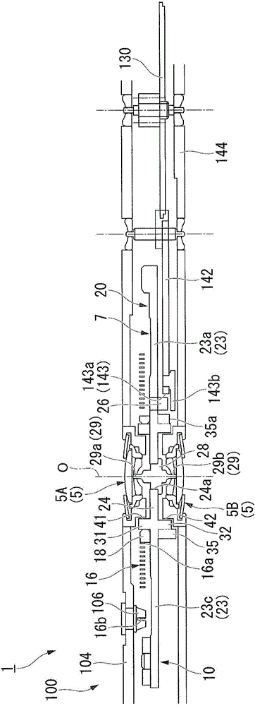
[0115] Image 6 It is a side sectional view of the movement of the timepiece of 2nd Embodiment.
[0116] In the above-mentioned first embodiment, the inner pile 18 is externally fitted and fixed on the first connecting portion 31 of the balance wheel 20 .
[0117] In contrast, as Image 6 As shown, the second embodiment differs from the first embodiment in that the collet 18 is fixed to the connection portion 24 of the balance wheel 20 .
[0118] In addition, below, description is abbreviate|omitted about the structure similar to 1st Embodiment.
[0119] A fitting recess 25 is formed in the coupling portion 24 of the balance wheel 20 . The fitting recess 25 is recessed in the axial direction. In addition, the fitting recess 25 may penetrate the balance wheel 20 .
[0120] The collet 18 is formed with a fitting convex portion 18a. When the collet 18 is arranged coaxially with the central axis O, the fitting convex por...
no. 3 approach
[0124] Next, a third embodiment will be described.
[0125] Figure 7 It is a side sectional view of the movement of the timepiece of 3rd Embodiment.
[0126] In the above-mentioned first embodiment, the inner pile 18 is externally fitted and fixed on the first connecting portion 31 of the balance wheel 20 .
[0127] In contrast, as Figure 7 As shown, in the third embodiment, the difference from the first embodiment is that the collet 18 is integrally formed with the balance wheel 20 .
[0128] In addition, below, description is abbreviate|omitted about the structure similar to 1st Embodiment.
[0129] The collet 18 is integrally formed with the balance wheel 20 on the front side of the movement 100 of the connecting portion 24 of the balance wheel 20 . The inner end 16 a of the hairspring 16 is connected to the collet 18 . That is, in the third embodiment, the collet 18 itself to which the inner end portion 16 a of the hairspring 16 is fixed is the first connection port...
PUM
 Abstract
Description
Claims
Application Information
PatSnap Eureka turns technology decisions into work you can execute. Powered by our Innovation Knowledge Graph, it runs expert workflows across engineering, life sciences, materials and intellectual property. Get your review-ready output in minutes.


