Fault injection device

A fault injection and fault technology, applied in the direction of electrical testing/monitoring, etc., can solve problems such as false reporting of the electronic control module under test, troublesome definition and editing of fault signals, failure to guarantee the pulse cycle of square wave signals or the integrity of analog signals, etc. To achieve the effect of synchronization

Active Publication Date: 2015-11-25
SAIC GENERAL MOTORS +1
View PDF3 Cites 20 Cited by
  • Summary
  • Abstract
  • Description
  • Claims
  • Application Information

AI Technical Summary

Problems solved by technology

[0003] The fault injection form of existing fault injection devices mostly adopts array relays, and injects fault signals through hard-wired changes. The disadvantage of this is that it cannot guarantee that each pulse cycle of the injected square wave signal or analog signal is complete, and the measured voltage Therefore, the control module may report errors; and the fault injection device is only for several common fault modes, such as short circuit and open circuit, etc., and has not studied the faults such as signal frequency, amplitude and duty cycle; in addition, the existing The fault signal of the scheme is used as an external input and is independent of the fault diagnosis module. Therefore, it will be very troublesome to define and edit the fault signal

Method used


Image

  • Fault injection device
  • Fault injection device
  • Fault injection device

Examples


Embodiment Construction

[0052] Introduced below are some of the various embodiments of the invention, intended to provide a basic understanding of the invention. It is not intended to identify key or critical elements of the invention or to delineate the scope of protection.

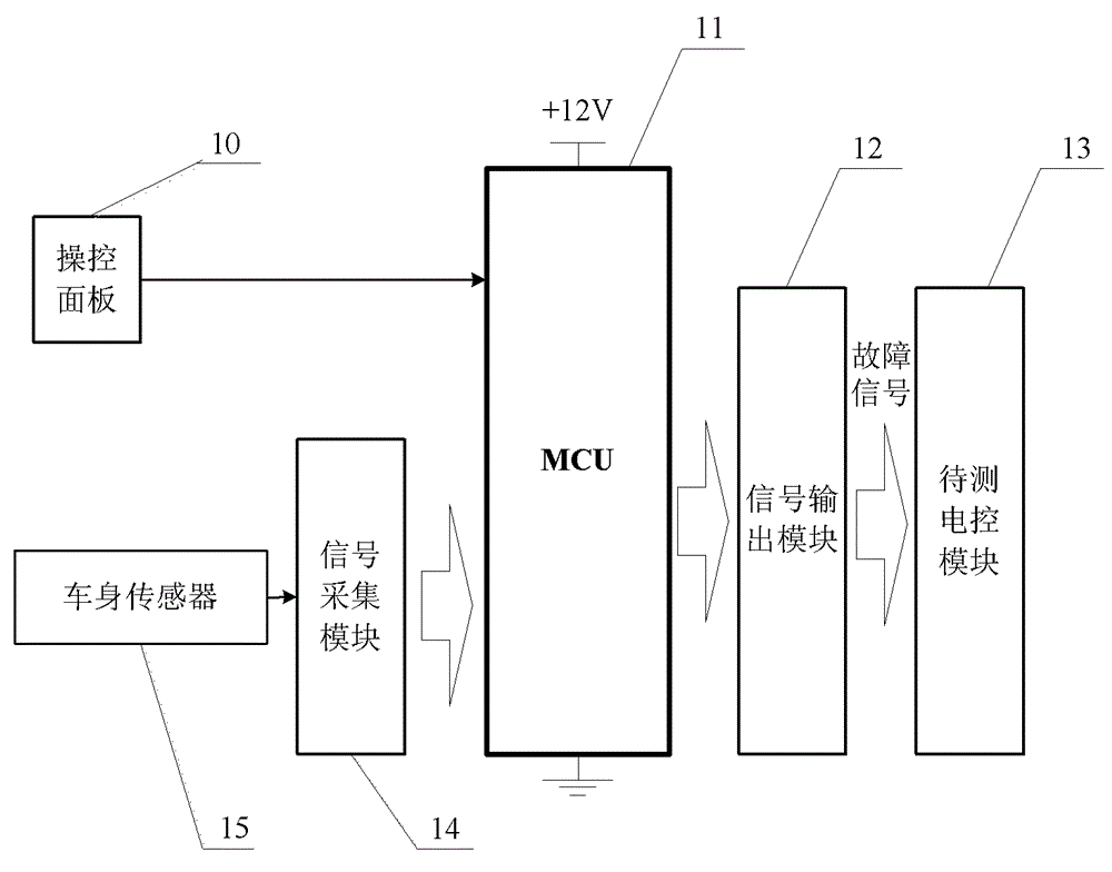
[0053] figure 1 is a structural block diagram of the fault injection device of the present invention. Refer below figure 1 The fault injection device of the present invention will be described.

[0054] Such as figure 1 As shown, the fault injection device of the present invention has: an operation panel 10, which is used to set the type of fault signal that needs to be injected; The structural part of the fault injection device, but refers to the signal of the sensor on the vehicle body) to filter and shape the original signal to input the following MCU; MCU (microprocessor) 11, in the case of fault injection mode, according to the slave operation The type of the fault signal that needs to be injected is received by the p...


PUM


Abstract

The invention relates to a fault injection device. The fault injection device comprises an operation panel used for setting a type of a fault signal needing injection, a signal collection module used for filtering and shaping a signal from a vehicle sensor to generate an original signal and inputting the original signal to an MCU, an MCU for processing the signal outputted from the signal collection module to generate a fault injection signal meeting the type of the fault signal needing injection as an output signal according to the type of the fault signal needing injection received by the operation panel in a situation that there is a fault injection mode or employing the original signal from the signal collection module as an output signal directly in a situation that there is not a fault injection mode, and a signal output module for receiving the output signal from the MCU and outputting a square wave signal or a simulation signal to an electric control module to be detected. By utilization of the fault injection device, fault injection with various types can be achieved.

Description

technical field [0001] The invention relates to the field of fault testing of vehicle electronic systems, in particular to a fault injection device for simulating fault injection of vehicle electronic systems. Background technique [0002] At present, the functions of electronic control modules equipped on vehicles are becoming more and more complex. The working status of some modules (electrically controlled power steering system EPS) directly affects driving safety, and wheel speed sensors and torque sensors are often important inputs for these modules, so , it is necessary to test the fault tolerance and coping strategy of this type of module when the sensor fails. [0003] The fault injection form of existing fault injection devices mostly adopts array relays, and injects fault signals through hard-wired changes. The disadvantage of this is that it cannot guarantee that each pulse cycle of the injected square wave signal or analog signal is complete, and the measured v...

Claims


Application Information

Patent Timeline
Patent Type & Authority Applications(China)
IPC IPC(8): G05B23/02
CPCG05B23/02
Inventor 杨洪福王雷雷尚世亮朱玙熹李壮运马凯
Owner SAIC GENERAL MOTORS
Why Eureka
Try Eureka