Residual image elimination method, drive system and display device

A drive system and afterimage technology, applied to static indicators, instruments, etc., can solve problems such as limited afterimage elimination effect and failure to display normally, and achieve good elimination effect, image afterimage elimination, and precise shake control

Inactive Publication Date: 2015-11-25
BOE TECH GRP CO LTD +1
View PDF6 Cites 9 Cited by
  • Summary
  • Abstract
  • Description
  • Claims
  • Application Information

AI Technical Summary

Problems solved by technology

[0005] However, the above methods have their own disadvantages: method ① cannot be displayed normally when using the elimination graphics to eliminate afterimages
Method ③Periodically adjusting the resistance has a limited effect on eliminating afterimages

Method used


Image

  • Residual image elimination method, drive system and display device
  • Residual image elimination method, drive system and display device
  • Residual image elimination method, drive system and display device

Examples


Embodiment 1

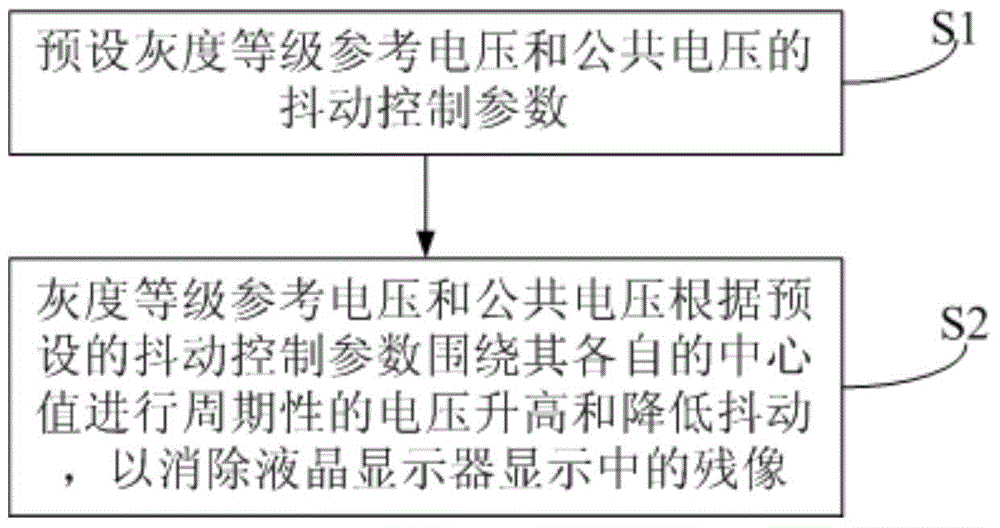
[0049] This embodiment provides a method for eliminating afterimages, such as figure 1 shown, including:

[0050] Step S1: Presetting the dithering control parameters of the gray scale reference voltage and the common voltage.

[0051] In this step, the dithering control parameters of the preset gray scale reference voltage include: the center value of the preset gray scale reference voltage; the dithering period, dithering range, dithering amplitude and the gray scale to be dithered of the preset gray scale reference voltage; order. The jitter control parameters of the preset common voltage include: a central value of the preset common voltage; a jitter period, a jitter range and a jitter amplitude of the preset common voltage.

[0052] Wherein, the dithering period refers to the time taken for the gray scale reference voltage or the common voltage to return to the respective central value after the voltage rises and dithers from the respective central value. The dithering...

Embodiment 2

[0084] This embodiment provides a method for eliminating afterimages. The difference from Embodiment 1 is that, as Figure 7 shown, including:

[0085] Step S1': preset the dithering control parameters of the gray scale voltage.

[0086] This step includes: setting the grouping parameters of the gray-scale voltage; presetting the dithering period, dithering range, dithering amplitude and gray scales to be dithered of the gray-scale voltage.

[0087] Wherein, the dithering period refers to the time taken for the gray scale voltage to return to its central value after the voltage increases or decreases after dithering from the central value. The dithering range refers to the difference between the maximum value and the minimum value of the gray scale voltage within one dithering period. The jitter amplitude refers to the variation amount of the voltage of two adjacent jitters of the gray scale voltage. The gray scale that needs to be dithered refers to the voltage value of th...

Embodiment 3

[0105] This embodiment provides a method for eliminating afterimages. The difference from Embodiment 1 is that Figure 11 As shown, it includes: step S1 ″: preset the dithering control parameters of the gray level reference voltage and the common voltage.

[0106] This step specifically includes:

[0107] Step S10: Pre-store a mapping table of different temperature ranges of the ambient temperature of the liquid crystal display and corresponding dithering control parameters of the gray scale reference voltage and the common voltage.

[0108] In this step, the different temperature ranges of the ambient temperature of the liquid crystal display correspond to a different grayscale reference voltage and the jitter control parameters of the common voltage, and the jitter control parameters of each grayscale reference voltage and common voltage correspond to control generation A set of grayscale reference voltages and a common voltage.

[0109] Step S2 ″: The gray level reference...


PUM


Abstract

The invention provides a residual image elimination method, a drive system and a display device. The residual image elimination method comprises the steps that gray scale level reference voltage and / or common voltage or gray scale voltage jitter control parameters are preset; and voltage boosting and / or jitter reducing are / is performed on gray scale level reference voltage and / or common voltage or gray scale voltage according to the preset jitter control parameters so that residual images displayed in a liquid crystal display can be eliminated. According to the residual image elimination method, jitter control of gray scale level reference voltage and / or common voltage or gray scale voltage is enabled to be more accurate so that the residual images displayed in the liquid crystal display can be eliminated, and the elimination effect of the residual images is enabled to be better. Normal display of the liquid crystal display is not influenced by the residual image elimination method.

Description

technical field [0001] The present invention relates to the field of display technology, in particular to a method for eliminating afterimages, a drive system and a display device. Background technique [0002] Among flat panel displays, liquid crystal displays are widely used in information devices such as mobile phones, computers, televisions, and personal digital assistants due to their thinness, light weight, low power consumption, and low electromagnetic radiation. [0003] Afterimage is one of the obvious defects of current LCDs. The so-called afterimage means that the LCD monitor displays the same fixed picture for a long time. When the picture is switched to the next picture, the image of the previous picture will remain vaguely. The ions in the panel will move to the upper and lower substrates of the liquid crystal along the direction of the electric field, and gather on the alignment layer. The gathered ions will generate static electricity. When the static electri...

Claims


Application Information

Patent Timeline
Patent Type & Authority Applications(China)
IPC IPC(8): G09G3/36
Inventor 闫龙
Owner BOE TECH GRP CO LTD
Why Eureka
Try Eureka