
Switches capable of suppressing arcs

A technology for suppressing arcs and switches, applied in electrical components and other directions, can solve problems such as reducing switch life, causing accidents, affecting switch feel, etc., and achieves the effects of low manufacturing cost, simple structure, and improved service life and reliability.

Active Publication Date: 2017-09-26
NINGBO BULL ELECTRIC CO LTD
View PDF6 Cites 0 Cited by
  • Summary
  • Abstract
  • Description
  • Claims
  • Application Information

AI Technical Summary

Problems solved by technology

The existing problems are: [1] Grease has the negative effect of strengthening the arc. If the amount is not accurate, the degree of ablation of the rocker body will increase, which will reduce the life of the switch and cause accidents; [2] Solid grease hardens at low temperature, hindering the The normal activity of the switch rocker assembly makes the switch unable to be turned on normally, and also affects the feel of the switch; [3] Oiling will increase labor costs, material costs, production equipment costs and other production costs

Method used


Image

  • Switches capable of suppressing arcs
  • Switches capable of suppressing arcs
  • Switches capable of suppressing arcs

Examples


Embodiment 1

[0026] Embodiment 1: This embodiment is a switch with a current of 10A and below,

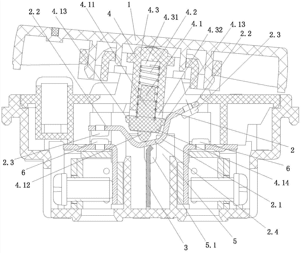
[0027] Such as figure 1 As shown, the present invention includes a switch button 1, a seesaw assembly 2, an incoming line terminal 3, a drive unit 4, a seesaw positioning member 5, and a static contact 6;

[0028] The rocker assembly 2 includes a rocker body 2.1. The middle part of the rocker body is U-shaped. The two side walls of the U-shape in the middle of the rocker body are respectively folded outward to form a rocker flange 2.2. The rocker flange is fixed with a movable contact. Head 2.3; the lower surface of the middle part of the rocker body is supported on the upper end of the incoming terminal 3, and the front and rear ends of the middle part of the rocker body 2.1 are provided with positioning protrusions 2.4; the positioning protrusions 2.4 extend on the positioning seat 5 of the rocker body inside the seesaw positioning groove 5.1;

[0029] The driver part 4 includes a drive rod...

Embodiment 2

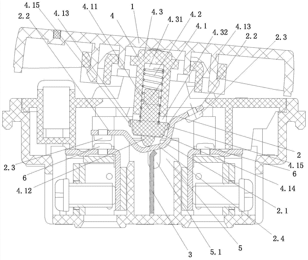
[0034] Such as figure 2 As shown, the difference between the second embodiment and the first embodiment is that in the second embodiment, the end of the position-limiting protrusion 4.13 is fixed with an elastic element 4.15, and the elastic coefficient of the elastic element 4.15 is less than five times the elastic coefficient of the spring 4.2. One-third, in this embodiment, the elastic coefficient of the elastic element 4.15 is equal to one-sixth of the elastic coefficient of the spring 4.2, and the end surface of the elastic element 4.15 and the U-shaped side wall in the middle of the seesaw body are always in contact with each other.

Embodiment 3

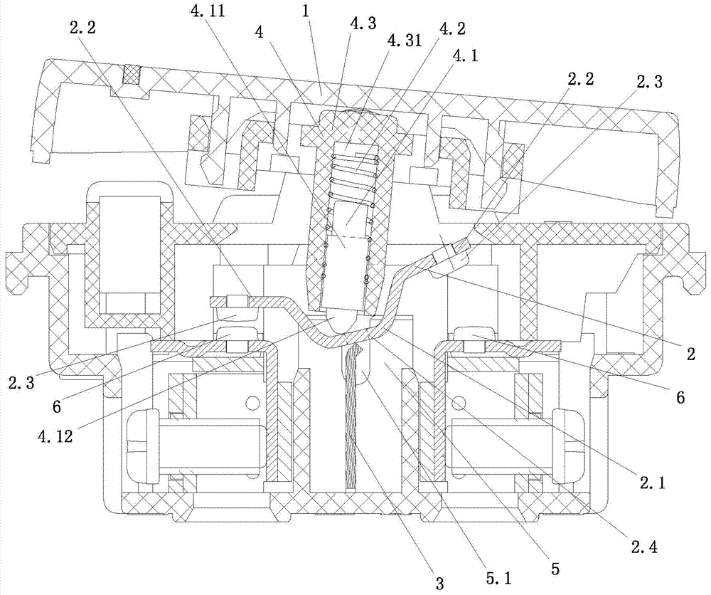
[0036] Such as image 3 As shown, the difference between this embodiment and Embodiment 1 is that before the switch is turned on or off, the U-shaped distance between the outer surface of the lower end of the transition piece 4.3 and the middle part of the seesaw body will be the same as that of the static contact 6. The side wall of the moving contact 2.3 that is touched is connected; that is, before the switch is turned on or off, the moving and static contacts that were originally in the state of contact are separated, and the other moving contact is connected to the other. The static contact approaches and finally connects with another static contact; during this period, the U-shaped side wall of the middle part of the seesaw body close to the side where the moving and static contacts are separated from each other is in contact with the transition piece 4.3, and the drive rod 4.1 The lower end of the U-shaped bottom in the middle of the rocker body slides toward the side c...


PUM

PropertyMeasurementUnit
Diameteraaaaaaaaaa
Diameteraaaaaaaaaa

Abstract

A switch capable of arc suppression comprises a switch button, a warped plate assembly, a wire inlet terminal, a driving element subassembly, a warped plate positioning element and a static contact, wherein the warped plate comprises a warped plate body, the middle of the warped plate body is of a U shape, the driving element subassembly comprises a driving rod, a spring and a transition element, the upper end of the transition element is connected with the switch button, a cylindrical accommodating recessed cavity is arranged on the transition element, the upper end of the driving rod is arranged in the accommodating recessed cavity, the upper end of the spring props against the bottom of the accommodating recessed cavity, the lower end of the spring props against the driving rod, and the end part of the lower end of the driving rod props against the bottom of the U shape at the middle of the warped plate body. During switch connection or disconnection process, the driving element subassembly can be contacted and connected with the side wall of a movable contact which is far away from the U shape at the middle of the warped plate body and is in contact with the static contact, thus, jumping between the warped plate body and the upper end of the ire inlet terminal and between the movable contact and the static contact can be prevented or reduced greatly, switching arc can be greatly reduced, and the service life of the switch is prolonged.

Description

technical field [0001] The invention relates to an electrical device, in particular to a switch capable of suppressing electric arcs. Background technique [0002] A switch is a common electrical device used to make or break current in one or more circuits. A commonly used switch includes a switch button, a rocker assembly, an incoming line terminal, a driver assembly, a rocker positioning member, and a static contact. Wherein the seesaw assembly includes a seesaw body, the middle part of the seesaw body is U-shaped, and the two side walls of the U-shape in the middle part of the seesaw body are respectively folded outwards to form a seesaw fold, and the seesaw fold is fixed with a moving contact; The lower surface of the middle part of the seesaw body is supported on the upper end of the incoming line terminal, and the front and rear ends of the middle part of the seesaw body are provided with positioning protrusions; The drive assembly includes the drive rod, spring and ...

Claims


Application Information

Patent Timeline
IPC IPC(8): H01H21/36
CPCH01H21/36
Inventor 孙卫华田赡民龚光辉申会员
Owner NINGBO BULL ELECTRIC CO LTD
Features
  • Generate Ideas
  • Intellectual Property
  • Life Sciences
  • Materials
  • Tech Scout
  • Unparalleled Data Quality
  • Higher Quality Content
  • 60% Fewer Hallucinations
Learn More