A radial waveguide power combiner and its assembly method

A power combiner and radial waveguide technology, applied in the field of electronics, can solve the problem of not being able to meet the transmission power requirements of millimeter-wave radar, unable to meet the transmission power requirements of millimeter-wave radar, and unable to effectively solve high power output, etc. Small loss, simple structure and easy implementation, low insertion loss effect

Active Publication Date: 2018-07-31
36TH RES INST OF CETC
View PDF4 Cites 0 Cited by
  • Summary
  • Abstract
  • Description
  • Claims
  • Application Information

AI Technical Summary

Problems solved by technology

For the application of power synthesis in the solid-state power transmission of millimeter-wave radar, the number of solid-state devices that can be synthesized is limited due to transmission line loss and circuit structure increasing non-linearly with the increase of the number of devices, which cannot meet the transmission power requirements of millimeter-wave radar.
The biggest advantage of space power combination is that the combination efficiency is basically independent of the number of solid-state devices, and it is more suitable for high-power output of multiple devices, but it also cannot meet the transmission power requirements of millimeter-wave radars, and cannot effectively solve the problem of high-power output in high-frequency bands. problem

Method used


Image

  • A radial waveguide power combiner and its assembly method
  • A radial waveguide power combiner and its assembly method
  • A radial waveguide power combiner and its assembly method

Examples


Embodiment Construction

[0040] In order to make the object, technical solution and advantages of the present invention clearer, the implementation manner of the present invention will be further described in detail below in conjunction with the accompanying drawings.

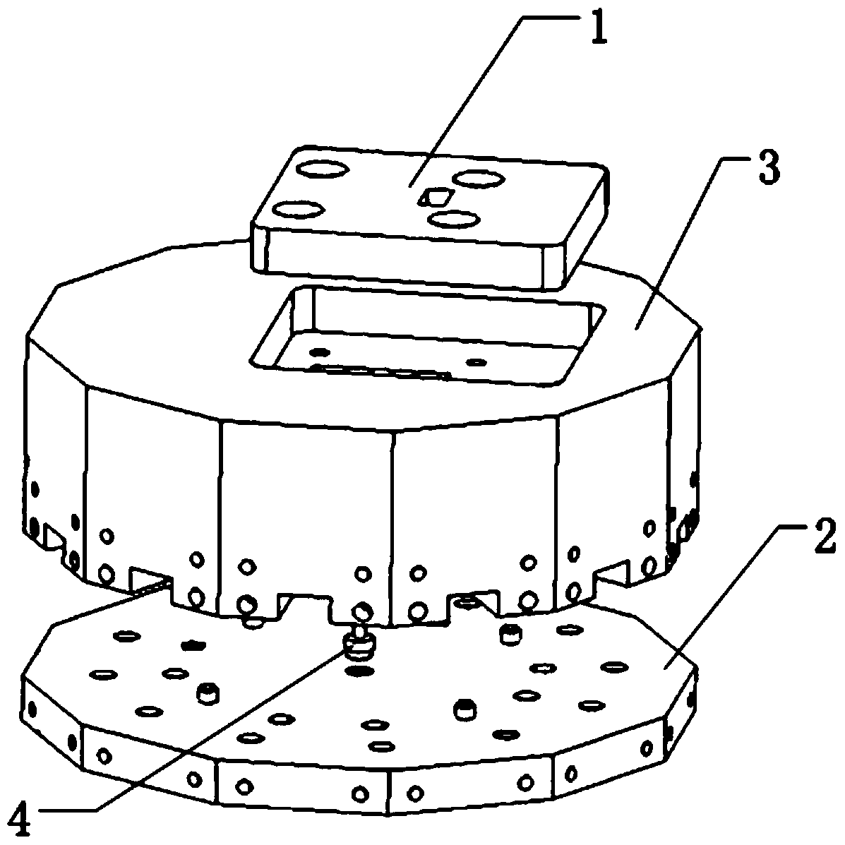
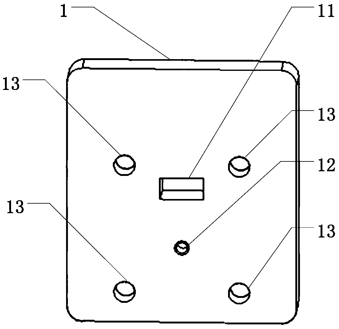
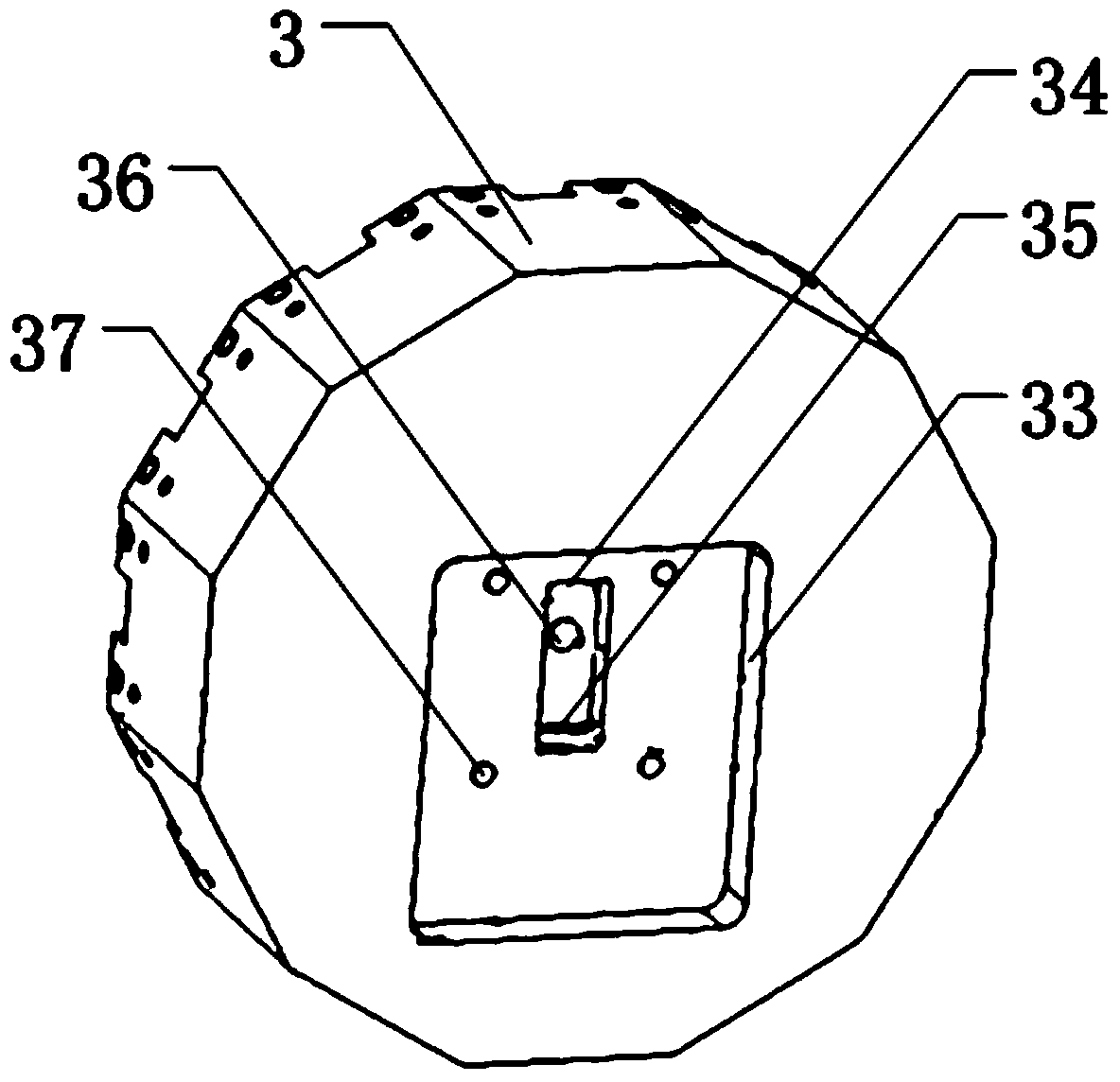
[0041] figure 1 A schematic diagram of a radial waveguide power combiner provided by an embodiment of the present invention, figure 2 The schematic diagram of the upper cover plate provided by the embodiment of the present invention, image 3 A schematic diagram of the upper half of the cavity block provided by the embodiment of the present invention, Figure 4 A schematic diagram of the lower half of the cavity block provided by the embodiment of the present invention, Figure 5 The schematic diagram of the lower cover plate provided by the embodiment of the present invention, Figure 6 The schematic diagram of the probe provided by the embodiment of the present invention, Figure 7 A schematic diagram of the assembly of the uppe...


PUM


Abstract

The invention discloses a radial waveguide power combiner and an assembly method thereof. The radial waveguide power combiner transmits microwaves in the waveguide input port to the radial waveguide through a probe, and then uses the characteristics of the radial waveguide to evenly distribute the microwaves. to each way. The probe adopts a plug-in fixing method, that is, the upper end of the probe is designed with a first positioning pin to be inserted into the first positioning hole of the upper cover, and the lower end of the probe is designed with a second positioning pin to be inserted into the second positioning hole of the lower cover. This design can not only ensure the overall structural stability, but also enable accurate positioning, reduce installation errors, and make the indicators more accurate. Compared with the existing synthesizer, the structure is simpler, more stable and easy to implement, the frequency band is wider, and the insertion loss is smaller, and it is more suitable for the application field of microwave and millimeter wave power synthesis.

Description

technical field [0001] The invention relates to the field of electronic technology, in particular to a radial waveguide power combiner and an assembly method thereof. Background technique [0002] In recent years, with the rapid development of the communication industry, the requirements for the bandwidth, transmission rate and transmission distance of the communication system are getting higher and higher. As an important part of the communication system, the power amplifier has increasing requirements on its bandwidth, efficiency and output power. However, due to the influence of the semiconductor physical characteristics of the millimeter-wave solid-state device itself and the limitations of processing technology, it is still difficult to produce high-power, low-noise and low-price millimeter-wave solid-state power devices. The research on millimeter-wave solid-state power combining technology has become the main way to solve this problem, and has a wide range of applica...

Claims


Application Information

Patent Timeline
Patent Type & Authority Patents(China)
IPC IPC(8): H01P5/12H01P11/00
Inventor 董亮蓝永海顾卫东
Owner 36TH RES INST OF CETC
Why Eureka
Try Eureka