
Stripping device of cable insulation shielding layer

A cable insulation and shielding layer technology, which is applied in the field of cable insulation and shielding layer stripping devices, can solve the problems of inconvenient tool replacement and height adjustment, low cutting precision of insulation layer, and reduced cable insulation, so as to improve cutting accuracy and facilitate The effect of high tool height and high safety

Active Publication Date: 2015-11-25
STATE GRID SHANDONG ELECTRIC POWER COMPANY WEIFANG POWER SUPPLY +1
View PDF12 Cites 9 Cited by
  • Summary
  • Abstract
  • Description
  • Claims
  • Application Information

AI Technical Summary

Problems solved by technology

Since the thickness of the insulating shielding layer is only 1-2mm, the insulating shielding layer must be completely stripped when making the cable terminal, and the internal cable structure cannot be damaged. Therefore, how to increase the speed of stripping the cable insulating shielding layer has become an urgent problem. In the prior art Generally, the stripping work is carried out manually. When the operator cuts the insulating shielding layer, the internal structure may be damaged, resulting in a decrease in the insulation of the cable and burying hidden dangers of accidents.
In addition, in order to solve this problem, people have invented a variety of cable insulation stripping tools, such as a cable sheath stripping tool that cuts the insulation layer along the axial direction of the cable. This stripping method is difficult to remove the cut insulation layer. Removal requires secondary cutting, the operation is more complicated, and it is not convenient for tool replacement and height adjustment, so the cutting accuracy of the insulating layer is low and the practicability is not strong

Method used


Image

  • Stripping device of cable insulation shielding layer
  • Stripping device of cable insulation shielding layer
  • Stripping device of cable insulation shielding layer

Examples


Embodiment Construction

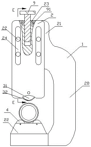
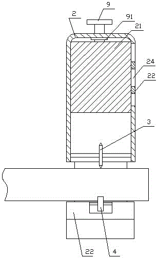
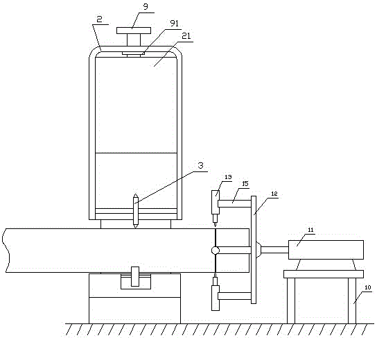
[0023] Refer to attached figure 1 , The cable insulation and shielding stripping device of the present invention includes a bracket 1, the upper part of the bracket 1 is slidably connected with a height-adjustable knife rest 2, the upper part of the bracket 1 is provided with a slider 21, and the knife rest 2 is slidably connected to the slider 21 . In this embodiment, the tool rest 2 is a U-shaped connecting plate, and the U-shaped connecting plate includes a top plate and two side plates that are affixed to the two ends of the top plate and extend downward. Adjusting screws 9 are installed between the top plate and the slider 21, and the slider 21 is provided with a screw hole with an upward opening, and the adjusting screw 9 passes through the top plate and is screwed in the above screw hole. The adjusting screw 9 is provided with a ring platform 91, and the ring platform 91 contacts with the lower surface of the top plate. Bearing 23 is installed between, and adjusting sc...


PUM


Abstract

The invention relates to a stripping device of a cable insulation shielding layer. A knife rest with adjustable height is connected with the upper part of a support in a sliding way, a knife installation wheel is arranged on the knife rest and can be used for annularly cutting a cable to be cut, two rollers are arranged at the lower part of the support and are in correspondence to the knife installation wheel, the rolling directions of the two rollers and the knife installation wheel are the same, an axial cutting device is arranged at the side part of the support, a knife is used for annularly cutting along the outer surface of a cable, the height of the knife rest is adjusted after cutting a certain depth, the cutting depth is adjusted according to demand, thus, the cutting accuracy of the cable insulation shielding layer can be improved, and the cut cable is axially cut by the axial cutting device so as to conveniently strip the insulation shielding layer. By such structure, secondary cutting and manual stripping work are avoided, the working efficiency is greatly improved, moreover, labor and time are saved, and the safety is high.

Description

technical field [0001] The invention relates to the field of cable laying tools, in particular to a device for stripping cable insulation and shielding layers. Background technique [0002] Substation maintenance, testing, and overhaul require the production of multiple cable terminals. Each cable terminal takes 3 hours to produce, and about 300 cable joints need to be produced each year, of which stripping the insulation shielding layer accounts for more than 60% of the total time. Since the thickness of the insulating shielding layer is only 1-2mm, the insulating shielding layer must be completely stripped when making the cable terminal, and the internal cable structure cannot be damaged. Therefore, how to increase the speed of stripping the cable insulating shielding layer has become an urgent problem. In the prior art Generally, the stripping work is performed manually. When the operator cuts the insulating shielding layer, the internal structure may be damaged, resultin...

Claims


Application Information

Patent Timeline
Patent Type & Authority Applications(China)
IPC IPC(8): H02G1/12
Inventor 钟贵森张涛张宏滨孟博张明岗张以宁陈伟涛董道玉李辉付强崔文生刘常明彭永磊王琳姜思坤
Owner STATE GRID SHANDONG ELECTRIC POWER COMPANY WEIFANG POWER SUPPLY
Learn More