Electric-wire protection device

A protection device and electric wire technology, which is applied in the direction of circuit devices, emergency protection circuit devices, emergency protection devices with automatic disconnection, etc., can solve problems such as smoke from wires, late hours, etc., and achieve the effect of maintaining reliability

Inactive Publication Date: 2015-11-25
SUMITOMO WIRING SYST LTD
View PDF7 Cites 3 Cited by
  • Summary
  • Abstract
  • Description
  • Claims
  • Application Information

AI Technical Summary

Problems solved by technology

[0007] However, according to the technology disclosed above, when the electric wire is a single electric wire, although the estimated temperature of the electric wire is properly calculated, for example, when the electric wire is bundled and assembled in a vehicle, there is a problem that it may not be possible to estimate the temperature of the electric wire appropriately. temperature worry
That is, when the electric wires are bundled and assembled, the actual electric wire temperature (actual temperature) may be higher than the estimated temperature due to the influence of heat from other electric wires. The problem that the temperature time is later than the time when the actual temperature reaches its upper limit allowable temperature
When this problem occurs, there is a possibility of smoke from the wire

Method used


Image

  • Electric-wire protection device
  • Electric-wire protection device
  • Electric-wire protection device

Examples


Embodiment approach

[0068] refer to Figure 1 to Figure 6 One embodiment according to the present invention will be described.

[0069] 1. Circuit structure

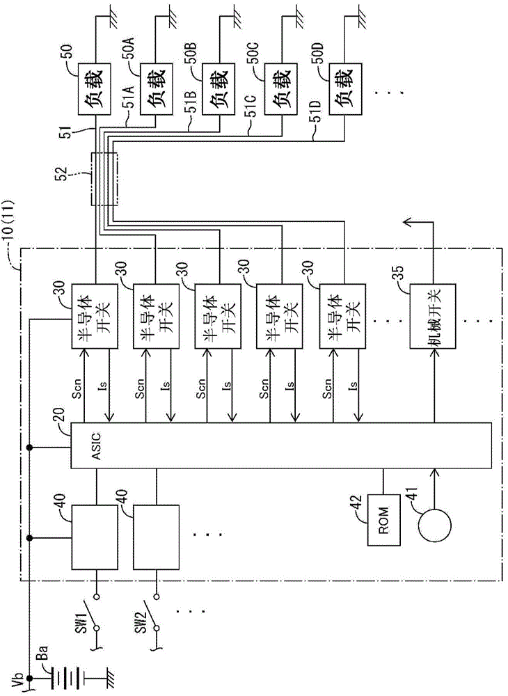
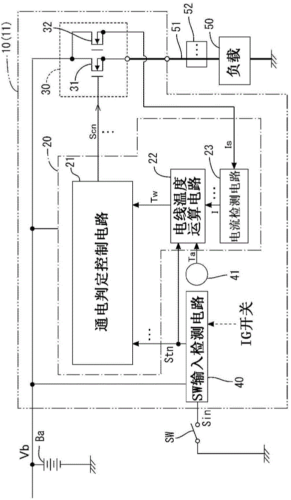
[0070] Such as figure 1 As shown, the wire protection device 10 is disposed between a power source Ba and a plurality of loads (50, 50A-50D). The electric wire protection device 10 protects an electric wire 51 corresponding to one load 50 among a plurality of loads, that is, an electric wire 51 used to supply electric power from a power source Ba to one load 50 .

[0071] Wire protection device 10 from a large aspect, such as figure 1 As shown, it includes a wire protection unit 20 , a plurality of semiconductor switch circuits (switch units) 30 , a plurality of SW (switch) input detection circuits 40 , an ambient temperature sensor (temperature detection unit) 41 and a ROM 42 . The wire protection device 10 is formed on a printed substrate 11 .

[0072] In addition, in this embodiment, the example in which the electric wire protection...


PUM


Abstract

An electric-wire protection device protects at least one electric wire among an electric-wire bundle that bundles a plurality of electric wires that are used to supply power to a plurality of loads from a power source Ba. Calculation circuit calculates an increased temperature of the electric wire from an initial temperature at the time that the estimate begins, based on a load current Is that has been detected and a thermal characteristic of the electric wire, and estimates the temperature of the electric wire by adding the increased temperature to the initial temperature. Current flow information supply portion supplies to the calculation circuit current flow information related to current flow to a load other than a subject load. Calculation circuit corrects the initial temperature by a correction value that corresponds to the current flow information that exists at the time the estimate begins.

Description

technical field [0001] The present invention relates to an electric wire protection device, and particularly relates to a technique for estimating the temperature of an electric wire based on the current flowing through the electric wire. Background technique [0002] Conventionally, as a technique for estimating the temperature of an electric wire based on a current flowing through the electric wire, for example, a technique disclosed in Patent Document 1 is known. Here, a technique is disclosed that calculates an estimated temperature of a conductor (wire) by accumulating temperature rises and temperature drops of the wire based on current flowing through the wire to calculate the temperature of the wire. [0003] prior art literature [0004] Patent documents: [0005] Patent Document 1: Japanese Patent Laid-Open No. 2007-295776 [0006] The problem to be solved by the invention [0007] However, according to the technology disclosed above, when the electric wire is a...

Claims


Application Information

Patent Timeline
IPC IPC(8): H02H5/04H02H7/26G01K1/20
CPCH02H6/00H02H7/228H02H3/085
Inventor 长滨崇裕
Owner SUMITOMO WIRING SYST LTD
Why Eureka
Try Eureka