Camera module and electronic device having same

A camera module and lens assembly technology, applied in the field of camera modules and electronic devices, can solve the problems of scalding the base, small operation space, unstable welding and the like

Inactive Publication Date: 2015-11-25
NANCHANG O FILM OPTICAL ELECTRONICS TECH CO LTD +3
View PDF1 Cites 15 Cited by
  • Summary
  • Abstract
  • Description
  • Claims
  • Application Information

AI Technical Summary

Problems solved by technology

However, the welding pads of this welding structure are arranged on the surface of the PCB, and the welding feet are welded perpendicular to the surface of the welding pads. There is no support around the welding feet, and the welding is not reliable; and the operating space is small, and the welding head is easy to touch the base and burn the base.

Method used


Image

  • Camera module and electronic device having same
  • Camera module and electronic device having same

Examples


Embodiment Construction

[0020] The following will clearly and completely describe the technical solutions in the embodiments of the present invention with reference to the accompanying drawings in the embodiments of the present invention. Obviously, the described embodiments are only some, not all, embodiments of the present invention. Based on the embodiments of the present invention, all other embodiments obtained by persons of ordinary skill in the art without making creative efforts belong to the protection scope of the present invention.

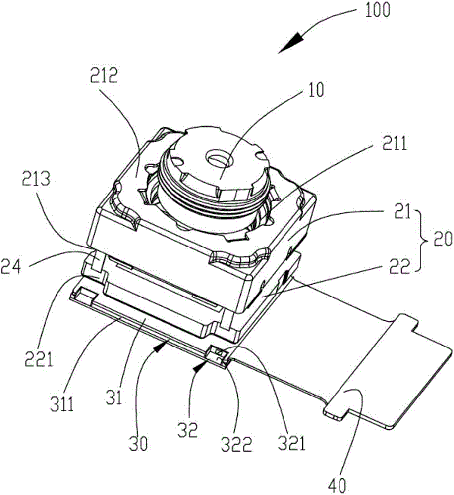
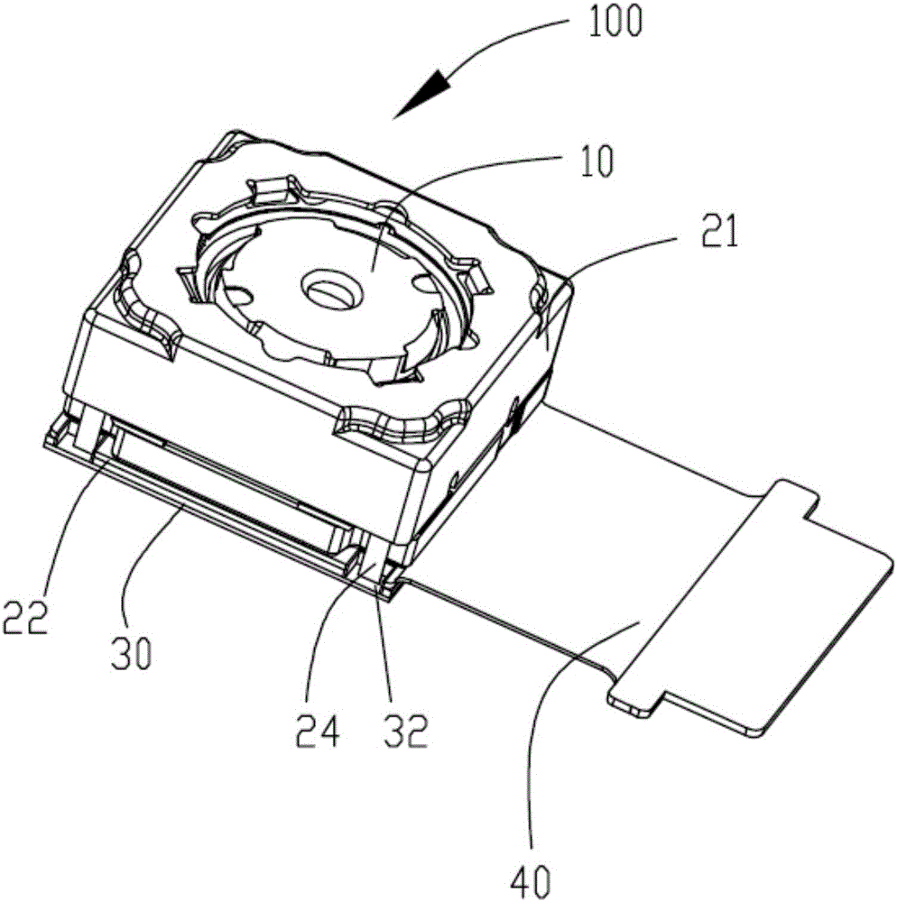
[0021] see figure 1 and figure 2 , a preferred embodiment of the present invention provides a camera module 100 , the camera module 100 includes a lens assembly 10 , a driver 20 and a circuit board 30 . The driver 20 includes a main body 21 and a base 22 . The base 22 is used for accommodating an infrared cut filter and an image sensor (not shown) of the camera module 100 . The main body 21 includes a top surface 212 with a through hole 211 and a bottom su...


PUM


Abstract

The invention provides a camera module. The camera module comprises a lens assembly, a driving member and a circuit board. The driving member comprises a main body and a base. The base is used for accommodating an infrared cut-off filter and an image sensor of the camera module. The main body comprises a top surface provided with a through hole and a bottom surface opposite to the top surface. The edge of the bottom surface is extended with welding legs. The circuit board comprises a first surface. The first surface is provided with grooves corresponding to the welding legs. The base is arranged on the first surface. The bottom surface of the main body is abutted against the base. The welding legs pass through the base and are inserted into and welded to the grooves. The lens assembly is arranged in the through hole of the main body. The invention also provides an electronic device.

Description

technical field [0001] The invention relates to a camera module and an electronic device with the camera module. Background technique [0002] At present, a traditional camera module includes a lens and a voice coil motor, and the voice coil motor is aligned with the mirror and drives the lens to move and can automatically focus. An infrared cut-off filter is arranged in the bracket of the voice coil motor, and the bracket is connected between the circuit board and the voice coil motor. An image sensor is installed between the bracket and the circuit board. The existing voice coil motors are generally fixed by soldering with the circuit board through the extended soldering legs of the shrapnel located at the bottom, as described in the document with the patent application number CN201220435501.9. However, the welding pads of this welding structure are arranged on the surface of the PCB, and the welding feet are welded perpendicular to the surface of the welding pads. There...

Claims


Application Information

Patent Timeline
Patent Type & Authority Applications(China)
IPC IPC(8): H04N5/225
Inventor 邬智文李巍王昕刘燕妮
Owner NANCHANG O FILM OPTICAL ELECTRONICS TECH CO LTD
Why Eureka
Try Eureka