
Backpack power sprayer

A sprayer, knapsack technology, applied in the field of knapsack power sprayer, can solve the problems of hand occupation, trouble, etc., and achieve the effect of good space efficiency

Active Publication Date: 2015-11-25
HONDA MOTOR CO LTD
View PDF5 Cites 3 Cited by
  • Summary
  • Abstract
  • Description
  • Claims
  • Application Information

AI Technical Summary

Problems solved by technology

As mentioned above, if you hold the hose with your hand and move it when you are not using the diffuser, your hands are not only occupied, but also more troublesome

Method used


Image

  • Backpack power sprayer
  • Backpack power sprayer
  • Backpack power sprayer

Examples


Embodiment

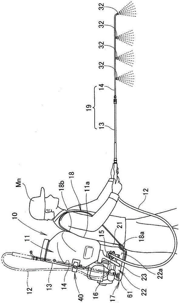
[0035] Next, the knapsack power sprayer of the embodiment will be described. figure 1 A case where the operator Mn performs spraying work with the backpack power sprayer 10 on his back is shown.

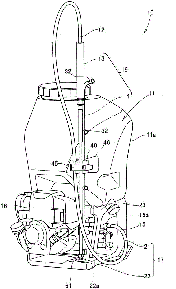
[0036] Such as figure 1 As shown, the knapsack power sprayer 10 is assembled with a liquid storage tank 11, a pump 15 for ejecting the liquid in the liquid storage tank 11, and an engine 16 for driving the pump 15, and can be carried by the operator Mn on his back. Working machine for spraying work. Hereinafter, this knapsack power sprayer 10 is simply referred to as "power sprayer 10".

[0037] Specific instructions, such as figure 1 with figure 2 As shown, the reservoir tank 11, the pump 15, and the motor 16 are assembled to a frame 17 that is substantially L-shaped in side view. The frame 17 is also called a carrying frame, and is composed of a front substantially vertical plate-shaped carrying portion 21 carried by the operator Mn and a substantially flat horizontal plate p...


PUM


Abstract

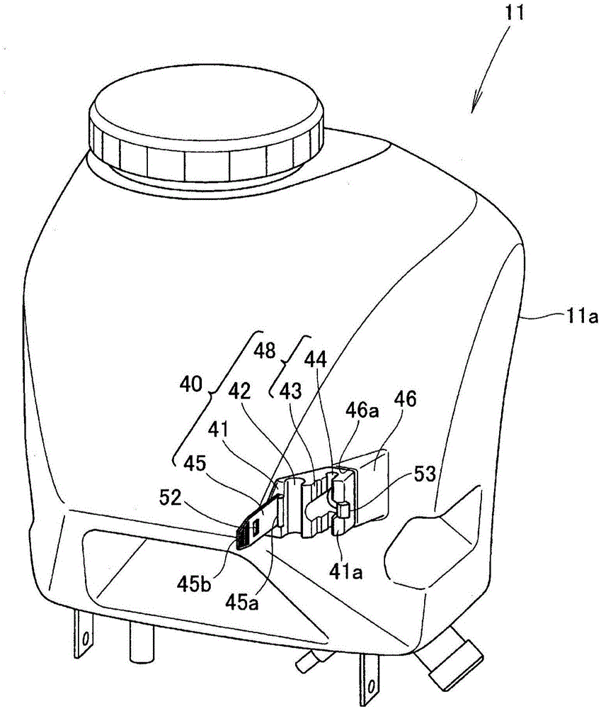
A backpack power sprayer (10) is provided with a liquid tank (11) and a power-driven pump (15). Liquid within the liquid tank is fed by the pump to a spray pipe (19) through a hose (12) and sprayed by the spray pipe. The backpack power sprayer is provided with a holding section (40). The holding section includes a hose-receiving recess (42) which receives a part of the hose, a pipe-receiving recess (48) which receives a part of the spray pipe, and a belt (45) which opens and closes the pipe-receiving recess and the hose-receiving recess.

Description

technical field [0001] The present invention relates to a knapsack power sprayer having a holder for holding a spreader tube. Background technique [0002] The knapsack-type power sprayer is a device in which the so-called sprayer main body, such as a liquid storage tank and a power-driven pump, is carried on the operator's back, and the liquid in the liquid storage tank is dispersed through a distribution pipe. When the operator carries the main body of the sprayer on his back while not performing spraying work, for example, he needs to hold the spraying pipe while moving, which is troublesome. In order to solve such a problem, according to Patent Document 1, a technique of hanging a spray pipe on a sprayer main body is known. [0003] The backpack-type power sprayer known in Patent Document 1 has an upward protrusion on the backpack frame. The discharge port of the pump is connected to the distribution pipe through a hose. A detachable holder is provided on the distribu...

Claims


Application Information

Patent Timeline
Patent Type & Authority Applications(China)
IPC IPC(8): A01M7/00F16L3/08B05B9/08
CPCB05B9/0855A01M7/0046B05B1/20B05B9/08F16L3/2235B05B9/085B05B15/00
Inventor 伊藤智树M·塔里尼T·塔娜万
Owner HONDA MOTOR CO LTD
Learn More