Torsional vibration damping transmission element

A technology of transmission components and transmission components, applied in the direction of rotation vibration suppression, spring/shock absorber, components with teeth, etc., can solve problems such as large preload torque, complex cost, large friction loss and meshing noise

Active Publication Date: 2015-11-25
PEZHO SITROEN AUTOMOBILS SA
View PDF8 Cites 0 Cited by
  • Summary
  • Abstract
  • Description
  • Claims
  • Application Information

AI Technical Summary

Problems solved by technology

[0007] These backlash compensation systems have limitations
For some severe applications, the aperiodic torque of the shaft is very large: clearance compensation systems or traditional vibration damping systems are not efficient or the structure is complex and costly
The preload torque of the backlash compensation system is large, which leads to large friction loss and meshing noise due to the great excitation of the gear teeth

Method used


Image

  • Torsional vibration damping transmission element
  • Torsional vibration damping transmission element
  • Torsional vibration damping transmission element

Examples


Embodiment Construction

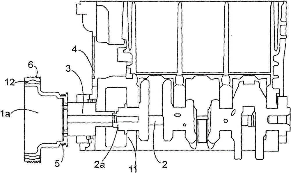
[0029] In the following, the transmission element is considered as a pulley connected to one end of the crankshaft, which represents the drive shaft. This is not restrictive, the transmission element may be any other element interposed between the driving shaft and the driven shaft.

[0030] as from figure 1 As can be seen in , the pulley 1 a is coupled to the end 2 a of the crankshaft 2 , opposite the hub 3 which passes through the opening in the housing surface 4 . The end of the hub 3 of the pulley 1a is inserted into the interior of the corresponding end 2a of the crankshaft 2 to be integrated with said end 2a by any method such as tightening screws and threads, forging, riveting or the like.

[0031] At the end 2a oriented towards the pulley 1a, the crankshaft 2 can be held by the last crankshaft bearing 11 of a set of crankshaft bearings inside the housing, the last crankshaft bearing 11 being the closest of the set of crankshaft bearings to the end 2a one. The last c...


PUM


Abstract

The present invention relates to a torsional vibration damping transmission element between a drive shaft and a driven shaft, this element limiting the vibrational excitation of the drive shaft transmitted to the driven shaft and reducing the dynamic forces passing through the element transmitting movement between the two shafts subjected to a rotational movement. The transmission element (1) is interposed between a drive shaft and a driven shaft transmitting rotational movement from the drive shaft to the driven shaft and is provided with a seismic mass (9, 9a) consisting of two portions, an elastomeric member (10) being interposed between the two portions, the seismic mass (9, 9a) being calculated to increase the inertia value of the transmission element (1) without a seismic mass (9, 9a) by a factor of between 2 and 5.

Description

technical field [0001] The invention relates to a torsional vibration damper transmission element between a driving shaft and a driven shaft, said element being able to limit the vibration excitation of the driving shaft transmitted to the driven shaft and to reduce the transmission between these two shafts subjected to rotational motion The power passing through an element in motion. Transmission elements are understood to mean all mechanical elements, such as pulleys or gears, which ensure transmission over a complete kinematic chain, which transmission elements may or may not be part of a driving or driven shaft. Background technique [0002] The invention is applied particularly advantageously, but without limitation, in the field of motor vehicles between a driving shaft and a driven shaft, in order to obtain an optimum mechanical strength of both shafts, and to improve acoustic and vibration performance. For example, the rotating drive shaft may be the crankshaft of a...

Claims


Application Information

Patent Timeline
IPC IPC(8): F16F15/14
CPCF16F15/1442F16H55/36F16H2055/366F16F15/14
Inventor P·莫克斯X·德科特
Owner PEZHO SITROEN AUTOMOBILS SA
Why Eureka
Try Eureka