Positioning draw die for connecting sheet

A technology for positioning stretching and connecting pieces, which is applied in the direction of metal processing equipment, forming tools, manufacturing tools, etc., can solve problems such as unstable stretching structures and mechanical deformation of connecting pieces, and achieve precise stretching and improve work efficiency.

Inactive Publication Date: 2015-12-02
DALIAN YILIAN METAL FORMING
View PDF10 Cites 0 Cited by
  • Summary
  • Abstract
  • Description
  • Claims
  • Application Information

AI Technical Summary

Problems solved by technology

[0002] Stamping die refers to a special process equipment that processes materials into parts in stamping processing. In the production of stamping parts, reasonable stamping forming technology, advanced molds, and efficient stamping equipment are three essential elements; According to the nature of the process, it can be divided into: the first is the blanking die, which separates the material along the closed or open contour line; such as blanking die, punching die, cutting die, slit die, trimming die and Cutting die, etc.; the second is the bending die to bend the sheet metal blank or other blanks along the straight line products, so as to obtain a workpiece mold with a certain angle and surname; the third is the drawing die, which is to make the sheet metal blank Opening hollow parts, or molds that further change the shape and size of hollow parts; the fourth type is forming dies, which directly copy the blank or semi-finished workpiece according to the shape of the convex and concave molds, and the material itself only produces local plastic deformation. Dies; such as bulging dies, shrinking dies, expanding dies, undulating forming dies, flanging dies and shaping dies, etc.; in the prior art, there is no stretching die for the connecting piece, and the general stretching die is easy to cause connection Mechanical deformation of the sheet and unstable tensile structure

Method used


Image

  • Positioning draw die for connecting sheet
  • Positioning draw die for connecting sheet

Examples


Embodiment Construction

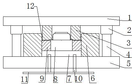
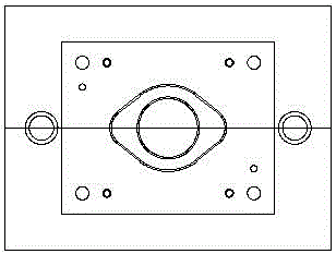
[0013] Such as figure 1 and figure 2 The connecting piece positioning stretching film shown includes an upper template 1 and a lower template 5, and guide sleeves 2 arranged on both sides of the bottom surface of the upper template, and a punch arranged on the bottom surface of the lower template 5 and installed between the guide sleeves 3, and one end of the guide post 4 cooperating with the guide sleeve, the other end of the guide post 4 is installed with the lower formwork 5, and the fixing plate 7 arranged above the lower formwork 5; and the die 6 arranged outside the fixing plate, And the jacking block 9 that is arranged on the inner side of the die, and the flanging punch 8 that is arranged on the inside of the jacking block, the punch 3 is provided with an upper positioning protrusion 12 near the die 6 side; the fixing plate 7 Install two sliding posts 10 on the top; the sliding posts 10 pass through the lower formwork 5 and the horizontal plate 11 and are fixedly ins...


PUM


Abstract

The invention discloses a positioning draw die for a connecting sheet. The positioning draw die comprises an upper die plate, a lower die plate, guide sleeves, a male die body, guide columns, a fixed plate, a female die body, a material ejecting block and a flanging male die body. The guide sleeves are arranged on the two sides of the bottom face of the upper die plate, and the male die body is mounted on the bottom face of the lower die plate and between the guide sleeves. One ends of the guide columns are mounted in cooperation with the guide sleeves, and the other ends of the guide columns and the lower die plate are mounted. The fixed plate is arranged above the lower die plate. The female die body is arranged outside the fixed plate. The material ejecting block is arranged on the inner side of the female die body. The flanging male die body is arranged on the inner side of the material ejecting block. An upper positioning protrusion is arranged on the side, close to the female die body, of the male die body. Two sliding columns are mounted at the top of the fixed plate. The sliding columns penetrate through the lower die plate, and the sliding columns and a cross plate are fixedly mounted. According to the positioning draw die for the connecting sheet, the male die body moves downwards to be embedded into the inner side of the female die body, and the upper portion of the male die body is limited through the positioning protrusion, so that the situation that in the drawing process of the connecting sheet, the connecting sheet is drawn excessively, or a drawing point is expanded outwards is avoided. Precise drawing can be achieved, and meanwhile work efficiency can be improved.

Description

technical field [0001] The invention relates to a stretching die, in particular to a connecting sheet positioning stretching film, which belongs to the technical field of dies. Background technique [0002] Stamping die refers to a special process equipment that processes materials into parts in stamping processing. In the production of stamping parts, reasonable stamping forming technology, advanced molds, and efficient stamping equipment are three essential elements; According to the nature of the process, it can be divided into: the first is the blanking die, which separates the material along the closed or open contour line; such as blanking die, punching die, cutting die, slit die, trimming die and Cutting die, etc.; the second is the bending die to bend the sheet metal blank or other blanks along the straight line products, so as to obtain a workpiece mold with a certain angle and surname; the third is the drawing die, which is to make the sheet metal blank Opening ho...

Claims


Application Information

Patent Timeline
IPC IPC(8): B21D37/10
Inventor 白林范久卫孙冬生
Owner DALIAN YILIAN METAL FORMING
Why Eureka
Try Eureka