Textile machine

A technology for textile machines, machine parts

Inactive Publication Date: 2009-06-17
RIETER INGOLSTADT SPINNEREI
View PDF6 Cites 0 Cited by
  • Summary
  • Abstract
  • Description
  • Claims
  • Application Information

AI Technical Summary

Problems solved by technology

[0003] A disadvantage in these textile machines is that the utilization of the known master-slave principle does not ensure that all drives operate in optimum synchronization with each other

Method used


Image

  • Textile machine
  • Textile machine
  • Textile machine

Examples


Embodiment Construction

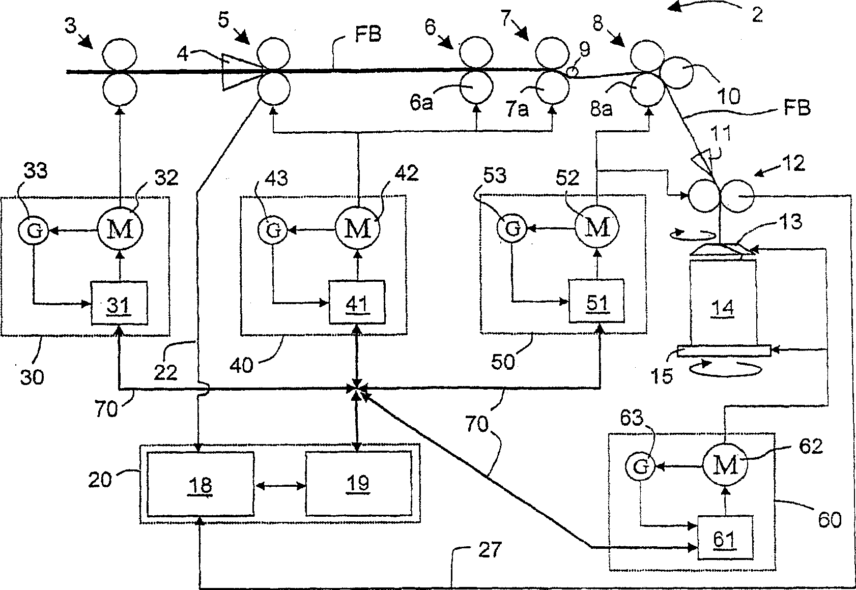
[0031] figure 1 Shows a side view of an adjustable draw frame with a drafting device 2 according to the invention as an example of a textile machine, comprising a pair of input rollers 6, a pair of central rollers 7, and a pair of output rollers 8. Upstream of the drafting device 2 is a pair of take-off rollers 3 for drawing one or several fiber strands (FB) from cans, not shown here. A sliver cross-section measuring device 5 in the form of a pair of scanning rollers upstream with a collecting funnel 4 is installed between the drafting device 2 and the pair of draw-off rollers 3 and provides a signal about the cross-section of at least one fiber strip (FB) . Instead of a pair of scanning rollers other cross-section measuring devices 5 are also possible, for example microwave resonators, capacitive sensors, ultrasonic sensors and the like. The fiber strip (FB) is drawn in a known manner under the effect of different rotational speeds of the roller pairs 6 , 7 , 8 . Between ...


PUM


Abstract

The invention relates to a textile machine, in particular to a carding machine, a drawing frame or a combing machine comprising at least two electrical drives ( 30, 40, 50, 60 ) whose operating modes are synchronised with respect to a master functionality for actuating the machine elements, in particular the drawing elements for fibre material, measuring elements, transporting elements and / or storing elements. Said machine also comprises at least one measuring device ( 33, 43, 53, 63, 34, 5, 9, 54 ) for measuring actual measurand values relating to actuation and / or to fibre material. The inventive carding machine is characterised in that at least one control and / or adjusting unit ( 19, 131, 141, 151, 161 ) makes it possible to modify the master function with respect to the actual values.

Description

technical field [0001] The invention relates to a textile machine, in particular a carding machine, a draw frame or a combing machine, comprising at least two electric drives whose rotational speed is in the driving of mechanical parts, especially fibrous material drafting parts, measuring parts, conveying parts The functional aspects of the main functions of the and / or storage components are coordinated with each other, and there is at least one measuring device for determining the actual value of the drive and / or fiber material-related measured values. Background technique [0002] The use of decentralized or individual drives has been known for a long time in the textile industry. For example, DE 29 41 612 C2 discloses a draw frame for combining and drafting the fiber sliver by means of a drafting device with pairs of rollers driven by separate electric motors whose rotational speed ratio can be adjusted via a frequency divider. A central processing unit continuously cal...

Claims


Application Information

Patent Timeline
IPC IPC(8): D01G31/00D01H5/32D01H5/42
CPCD01H5/42D01G31/006
Inventor 迈克尔·施特罗贝尔迈克尔·于丁彼得·登茨阿明·布伦纳
Owner RIETER INGOLSTADT SPINNEREI
Why Eureka
Try Eureka