Rubber pull machine

A tensile machine and rubber technology, applied in the direction of applying stable tension/pressure to test the strength of materials, measuring devices, instruments, etc., can solve the problems of tensile test failure, simple structure, low clamping force, etc., and achieve consistent pressing force , prevent slipping, good clamping force

Inactive Publication Date: 2020-01-17
宁国市中英橡胶有限公司
View PDF5 Cites 0 Cited by
  • Summary
  • Abstract
  • Description
  • Claims
  • Application Information

AI Technical Summary

Problems solved by technology

However, the current rubber tensile equipment has a simple structure, and the data obtained from the test generally have large errors, and the clamping force of the clamp used to clamp the rubber in the existing rubber tensile machine is low, which easily leads to the failure of the tensile test.

Method used


Image

  • Rubber pull machine
  • Rubber pull machine
  • Rubber pull machine

Examples


Embodiment Construction

[0020] Below in conjunction with accompanying drawing and embodiment, further elaborate the present invention. In the following detailed description, certain exemplary embodiments of the invention are described by way of illustration only. Needless to say, those skilled in the art would realize that the described embodiments can be modified in various different ways, all without departing from the spirit and scope of the present invention. Accordingly, the drawings and description are illustrative in nature and not intended to limit the scope of the claims.

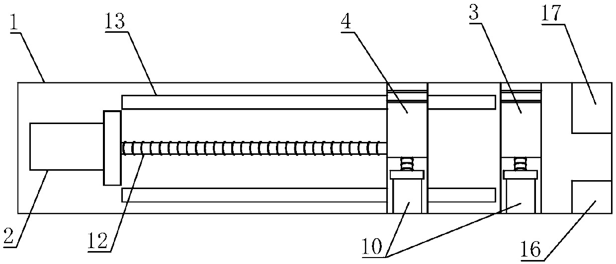
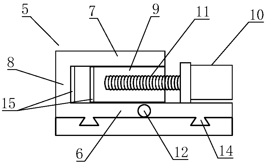
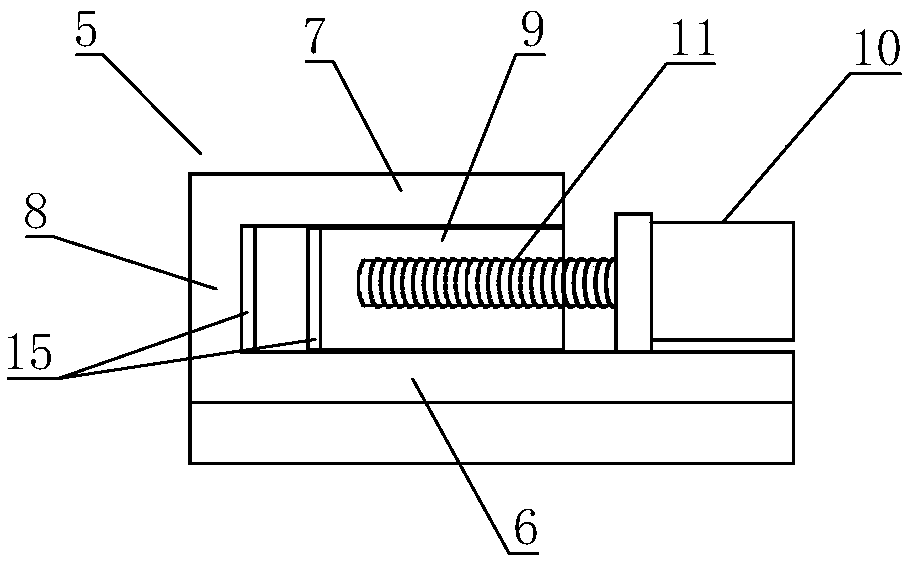
[0021] Such as figure 1 , figure 2 as well as image 3 As shown, a rubber tensile machine in this embodiment includes a machine base 1, one end of the machine base 1 is provided with a clamping device, and the other end of the machine base 1 is provided with a stretching servo motor 2, and the clamping device includes a fixing clip 3 and a movable clamp 4, the fixed clamp 3 is located on the side of the movable clamp...


PUM


Abstract

The invention discloses a rubber pull machine. The pull machine includes a machine seat. One end of the machine seat is provided with a clamping device, and the other end of the machine seat is provided with a stretching servo motor. The clamping device includes a fixed clamp and a moving clamp. Each of the moving clamp and the fixed clamp includes a U-shaped frame. The U-shaped frame includes a lower side wall, an upper side wall and a flat plate connecting one end of the upper side wall and one end of the lower side wall. Length of the lower side wall is greater than length of the upper sidewall. A pressing servo motor is disposed on one end portion of the lower side wall away from the flat plate. An output shaft of the pressing servo motor is fixedly connected with a pressing screw. Apressing block is in thread connection with a top end of the pressing screw away from the pressing servo motor. The U-shaped frame of the moving clamp is in sliding connection with the machine seat. Astretching screw is fixedly connected with an output shaft of the stretching servo motor. The U-shaped frame of the moving clamp is in thread connection with the stretching screw. The U-shaped frameof the fixing clamp is fixedly connected with the machine seat. According to the rubber pull machine of the invention, a degree of automation is high, and test data are accurate.

Description

technical field [0001] The invention relates to the technical field of industrial testing equipment, in particular to a rubber tension machine. Background technique [0002] Rubber refers to a highly elastic polymer material with reversible deformation. It is elastic at room temperature and can produce large deformation under a small external force. It can return to its original shape after removing the external force. At present, rubber products are widely used in industry and life aspect. During the production and processing of rubber, tensile testing is required to prevent unqualified products from entering the market. However, the current rubber tensile equipment has a simple structure, and generally the error of the tested data is large, and the clamping force of the clamps used to clamp the rubber in the existing rubber tensile machine is low, which easily leads to the failure of the tensile test. Contents of the invention [0003] The technical problem to be solve...

Claims


Application Information

Patent Timeline
Patent Type & Authority Applications(China)
IPC IPC(8): G01N3/08G01N3/04
CPCG01N3/04G01N3/08G01N2203/0003G01N2203/0017G01N2203/005G01N2203/0075G01N2203/04G01N2203/0676
Inventor 徐英木
Owner 宁国市中英橡胶有限公司
Why Eureka
Try Eureka