Safety protecting system for belt conveyor

A belt conveyor and safety protection technology, applied in the direction of conveyors, conveyor objects, conveyor control devices, etc., can solve the problems of complex wiring, short transmission distance, easy to be interfered, etc., to reduce wires and anti-interference ability. Strong, interference-avoiding effect

Active Publication Date: 2015-12-02
SICHUAN ZIGONG CONVEYING MACHINE GRP
View PDF5 Cites 5 Cited by
  • Summary
  • Abstract
  • Description
  • Claims
  • Application Information

AI Technical Summary

Problems solved by technology

However, this method has problems such as short transmission distance (generally,

Method used


Image

  • Safety protecting system for belt conveyor
  • Safety protecting system for belt conveyor

Examples


specific Embodiment 1

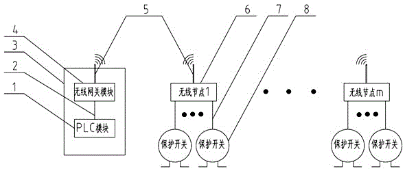
[0027] Such as figure 1 As shown, a belt conveyor safety protection system includes a control module and a signal acquisition module; the control module includes a PLC unit and a wireless gateway module connected to it; the signal acquisition module includes a deviation signal acquisition module and is connected to it The wireless signal transmitting antenna; when the belt deviates, the deviation signal acquisition module sends the deviation signal through the wireless signal transmitting antenna; the wireless gateway module receives the belt deviation signal sent by the wireless signal transmitting antenna.

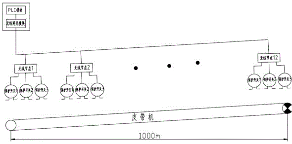
[0028] This specific embodiment is described in detail with a 1000-meter belt conveyor as an example, as figure 2 shown.

[0029] Each wireless signal transmitting antenna is a wireless node, and in this specific embodiment, each wireless node is equipped with a joint adapter line and a lightning protector. The power supply of wireless node and wireless gateway module...

specific Embodiment 2

[0035] The difference with Embodiment 1 is only that: on the basis of Embodiment 1, the signal acquisition module also includes an accident signal acquisition module. When an accident occurs and the accident signal acquisition module is triggered, the accident signal acquisition module will The accident signal is sent out through the wireless signal sending antenna; the wireless gateway module receives the accident signal sent by the wireless signal sending antenna.

[0036] The accident signal acquisition module is a pull rope switch, and every three to five pairs of pull rope switches define an accident address.

[0037] The pull rope switches are arranged in pairs on both sides of the belt, and a pair is arranged at intervals of 30 meters to 50 meters from one end of the belt to the other end. In this specific embodiment, a pair of pull rope switches is arranged every 30 meters along the belt conveyor, a total of 34 pairs. Define 3 pairs of pull rope switches as an address...

specific Embodiment 3

[0039] The difference with specific embodiment 1 and specific embodiment 2 is only that, in this specific embodiment, the signal acquisition module only includes the accident signal acquisition module, when an accident occurs and the accident signal acquisition module is triggered, the accident signal The acquisition module sends the accident signal through the wireless signal sending antenna; the wireless gateway module receives the accident signal sent by the wireless signal sending antenna. In this specific embodiment, a pair of pull rope switches is arranged every 30 meters along the belt conveyor, a total of 34 pairs. Define 3 pairs of pull rope switches as an address, and install 1 wireless node for address coding, a total of 12 wireless nodes.


PUM


Abstract

The invention provides a safety protecting system for a belt conveyor. The safety protecting system comprises a control module and a signal collecting module; the control module comprises a programmable logic controller (PLC) unit and a wireless gateway module connected with the PLC unit; the signal collecting module comprises an off-track signal collecting module and a wireless signal transmitting antenna connected with the off-track signal collecting module; when a belt is off tracking, the off-track signal collecting module transmits an off-track signal through the wireless signal transmitting antenna; the wireless gateway module receives the belt off-track signal transmitted by the wireless signal transmitting antenna. According to the whole belt conveyor, all address code signals on site can be transmitted back to a PLC system without control cables along the line, wire materials are reduced, the cost is reduced greatly, and interference is avoided.

Description

technical field [0001] The invention relates to a belt conveyor safety protection system, in particular to a belt conveyor safety protection system applicable to the fields of electric power, iron and steel, coal, water conservancy, chemical industry, metallurgy, building materials and the like. Background technique [0002] At present, belt conveyors are widely used in electric power, steel, coal, water conservancy, chemical industry, metallurgy, building materials and other fields. The safety protection device in the belt conveyor system is an indispensable part of the system design, and plays a vital role in the normal operation of the belt conveyor and the safety of personnel. However, with the development of belt conveyors towards longer and longer distances, enterprises have put forward higher requirements for conventional protection devices, for example: pull rope switches and deviation switches are required to have address coding functions. At present, the solution ...

Claims


Application Information

Patent Timeline
IPC IPC(8): B65G15/64B65G43/00
Inventor 牟宗魁李冰
Owner SICHUAN ZIGONG CONVEYING MACHINE GRP
Why Eureka
Try Eureka