Method of communicating a signal from a sensor, connected to a connector, to an auxiliary module

a sensor and connector technology, applied in the direction of programme control, coupling device connection, instruments, etc., can solve the problems of increasing the mass, increasing the number of circuits, etc., and achieve the effect of making the wire harness simple and lightweigh

Inactive Publication Date: 2008-04-08
YAZAKI CORP
View PDF13 Cites 6 Cited by
  • Summary
  • Abstract
  • Description
  • Claims
  • Application Information

AI Technical Summary

Benefits of technology

[0047]In the above configuration, the wire harness can be made simpler and more lig

Problems solved by technology

Secondly, an increase in the function of electronic vehicle equipment results in not only increasing the number of circuits but also enlarging the wire harness itself, so that an increase in the mass is incurred.
Thirdly, due to centralized control performed by the ECU, the ECU becomes enlarged as a result of an increase in the function of electronic vehicle equipment; the problem is that an increase in the mass (deterioration in fuel efficiency and driving performa

Method used


Image

  • Method of communicating a signal from a sensor, connected to a connector, to an auxiliary module
  • Method of communicating a signal from a sensor, connected to a connector, to an auxiliary module
  • Method of communicating a signal from a sensor, connected to a connector, to an auxiliary module

Examples


Embodiment Construction

[0059]A detailed description will now be given of an embodiment of the invention by reference to the accompanying drawings.

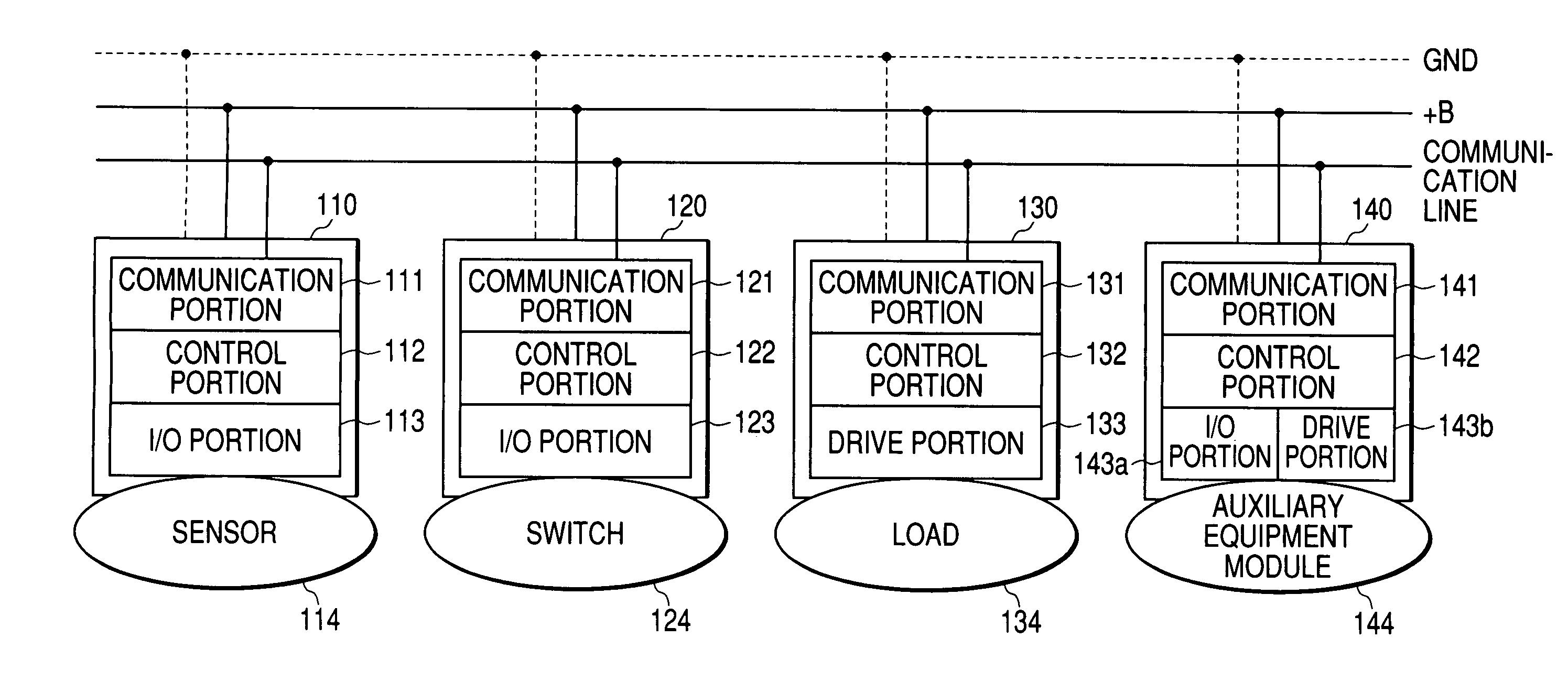
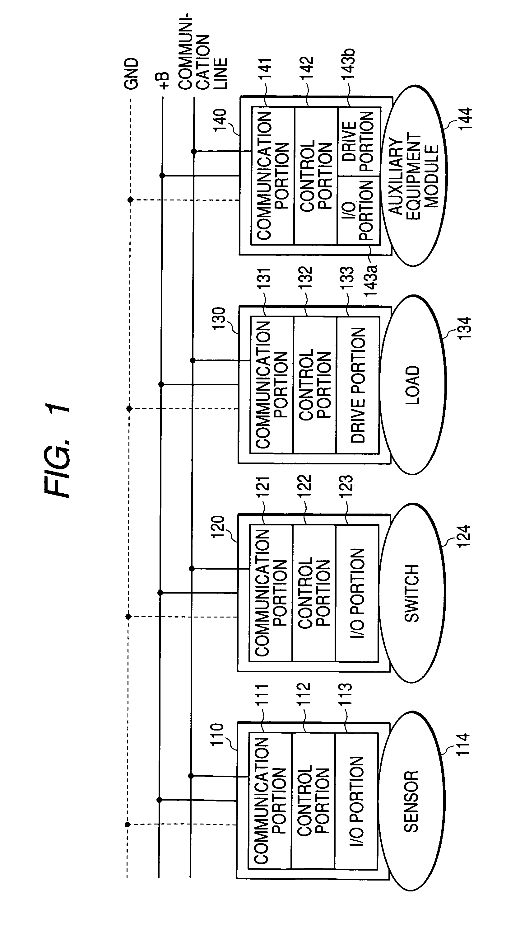
[0060]FIG. 1 is a functional block diagram showing the basic concept of an electronic connector according to the embodiment of the invention. An electronic connector 110 is directly connected to the connector of a sensor 114. The electronic connector 110 includes a communication portion 111, a control portion 112 and an I / O portion 113 on a built-in electronic board. An electronic connector 120 directly connected to the connector of a switch SW 124 also includes a communication portion 121, a control portion 122 and an I / O portion 123 on a built-in electronic board. An electronic connector 130 directly connected to a load (e.g., a lamp, a motor or the like) includes a communication portion 131, a control portion 132 and a drive portion 133 on a built-in electronic board. Further, an electronic connector 140 directly connected to an auxiliary equipment module 144...


PUM


Abstract

An electronic connector connected to a sensor or a switch, and communicating a signal through a common bus includes an I/O unit receiving a signal from the sensor or the switch, a control unit generating a control signal for controlling the driving of a load corresponding to the sensor or the switch according to the signal received from the I/O unit, and a communication unit having a function of decoding the control signal and transmitting the control signal to an equipment connected to the corresponding load through the common bus.

Description

BACKGROUND OF THE INVENTION[0001]The present invention relates to an intelligent electronic connector incorporating communication, control and input-output functions and / or a drive function and to an auxiliary equipment module.[0002]FIG. 10 is a functional block diagram showing a electronic control unit (ECU) for controlling electronic vehicle equipment in the related art. The ECU shown in FIG. 10 includes a power supply 204, a communication portion 201, a centralized control portion 202, an I / O (input / output): portion 213, an I / O portion 223 and a drive portion 233. The I / O portion 213 is connected via a connector 210 to a sensor 114 by a wire harness. The I / O portion 223 is connected via a connector 220 to a switch 124 by a wire harness. The drive portion 233 is connected via a connector 230 to a load 134 by a wire harness. Although ECUs 200 are mutually connected by way of multiplex communication, the load 134, the switch SW 124 and the like are connected to the ECU 200 by way of...

Claims


Application Information

Patent Timeline
IPC IPC(8): G06F1/00B60R16/02G05B15/00H01R13/66
CPCH01R13/665G05B2219/21076G05B2219/2637
Inventor NAGASAWA, KAZUMIOZAKI, TOSHIAKISHIMIZU, NORIHITO
Owner YAZAKI CORP
Why Eureka
Try Eureka