
Structure of electric energy metering assembly

An assembly structure and electric energy metering technology, applied in the direction of measuring electrical variables, measuring devices, measuring time integration, etc., can solve problems such as waste, bulkiness, and many lines

Inactive Publication Date: 2010-01-20
万叶琳
View PDF3 Cites 5 Cited by
  • Summary
  • Abstract
  • Description
  • Claims
  • Application Information

AI Technical Summary

Problems solved by technology

At present, most of the electric energy metering devices used by the electric power sector in the market are to install the electric energy meter and other metering devices separately in an independent meter box or install them in an independent meter box and then use other devices such as clamps to fix the single meter box. Assemble together; or install multiple electric energy meters in a large box structure, and then route them separately; if the date of authorization announcement is October 30, 2002, and the authorization announcement number is CN2519152Y utility model patent; the date of authorization announcement For April 26, 2002, the authorized announcement number is CN2497319Y and other utility models or invention patents, all disclose a kind of single-phase multi-user electric energy meter, they all have common shortcoming and deficiency: the one, relatively large, heavy, because There are many users and electric energy meters, so the box is naturally large and heavy; second, the cost is high; due to the large box, all of which are connected by wires, the amount of box materials and wires is huge, and resource consumption and waste are very serious; third, because the electric energy meter Many, many lines, miscellaneous, chaotic, bring considerable inconvenience to management and maintenance
At present, most of the meter boxes sold and used in the market have the above-mentioned problems. In the process of design, production, installation, use, management, maintenance, etc., it takes a lot of manpower, material resources, and financial resources, which increases the cost for users and power supply management departments. Does not meet the needs of building an energy-saving society in my country

Method used


Image

  • Structure of electric energy metering assembly
  • Structure of electric energy metering assembly
  • Structure of electric energy metering assembly

Examples


Embodiment Construction

[0035] The structure of an electric energy metering assembly provided by the present invention will be described in detail below in conjunction with the accompanying drawings.

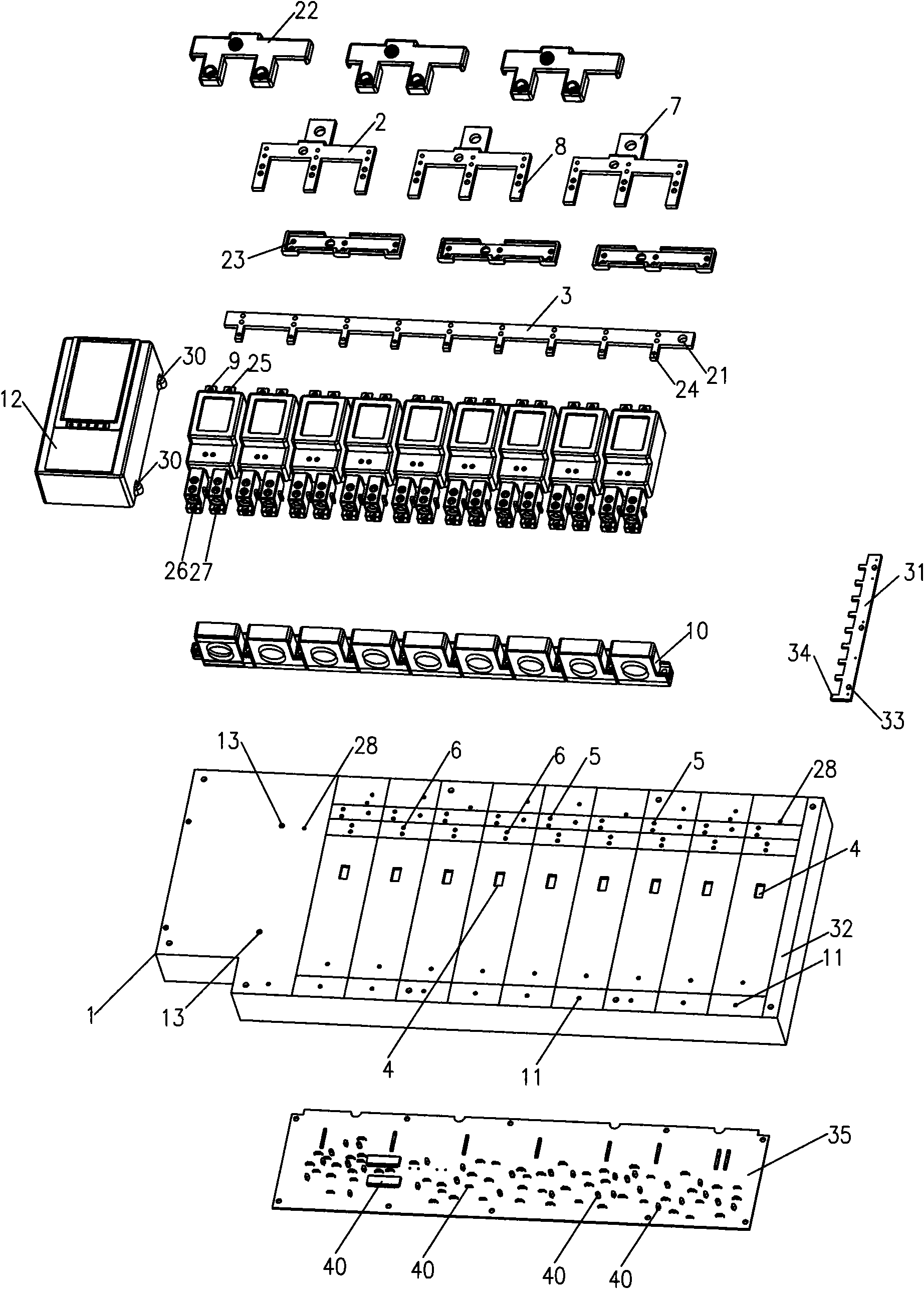
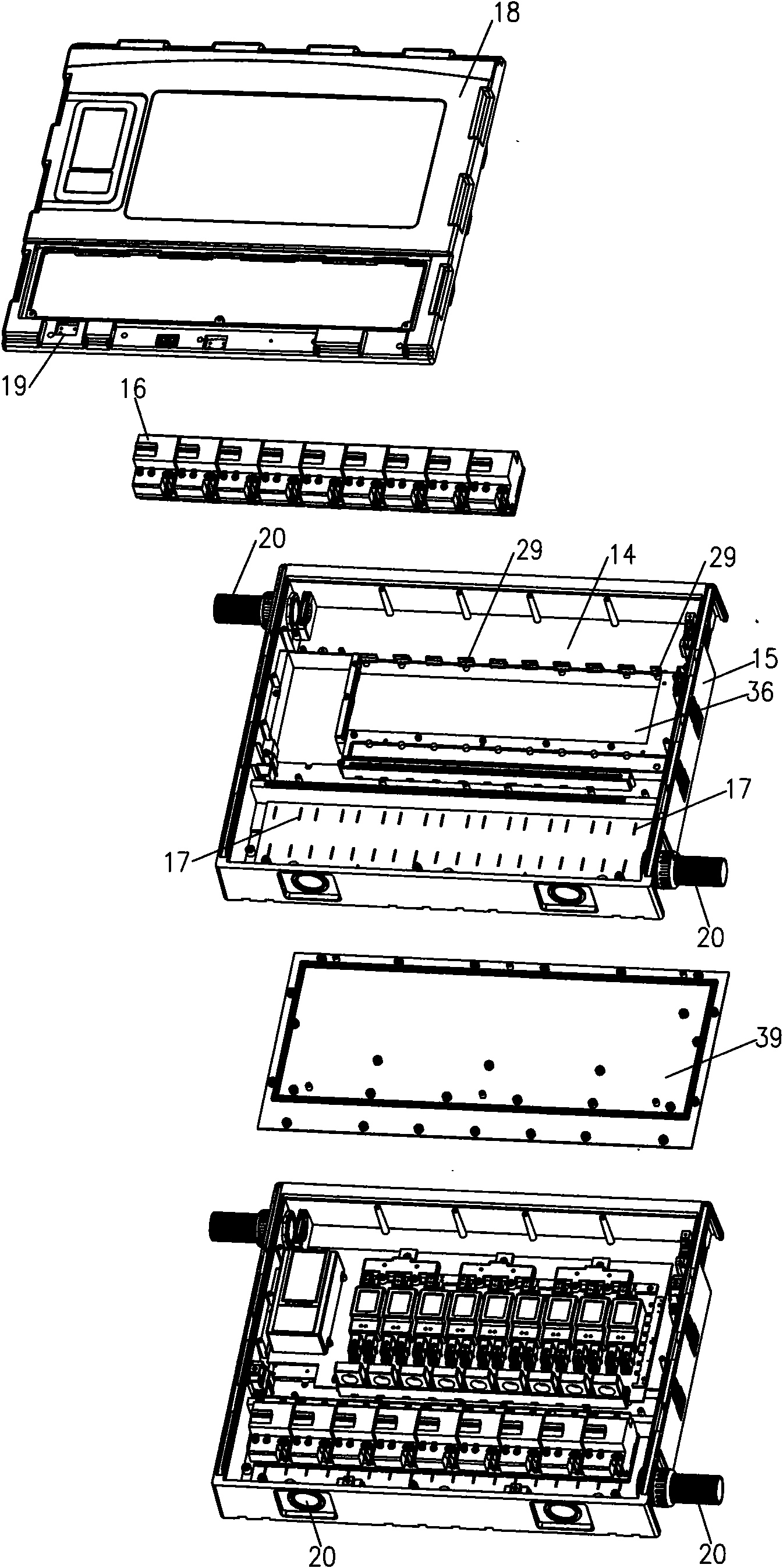
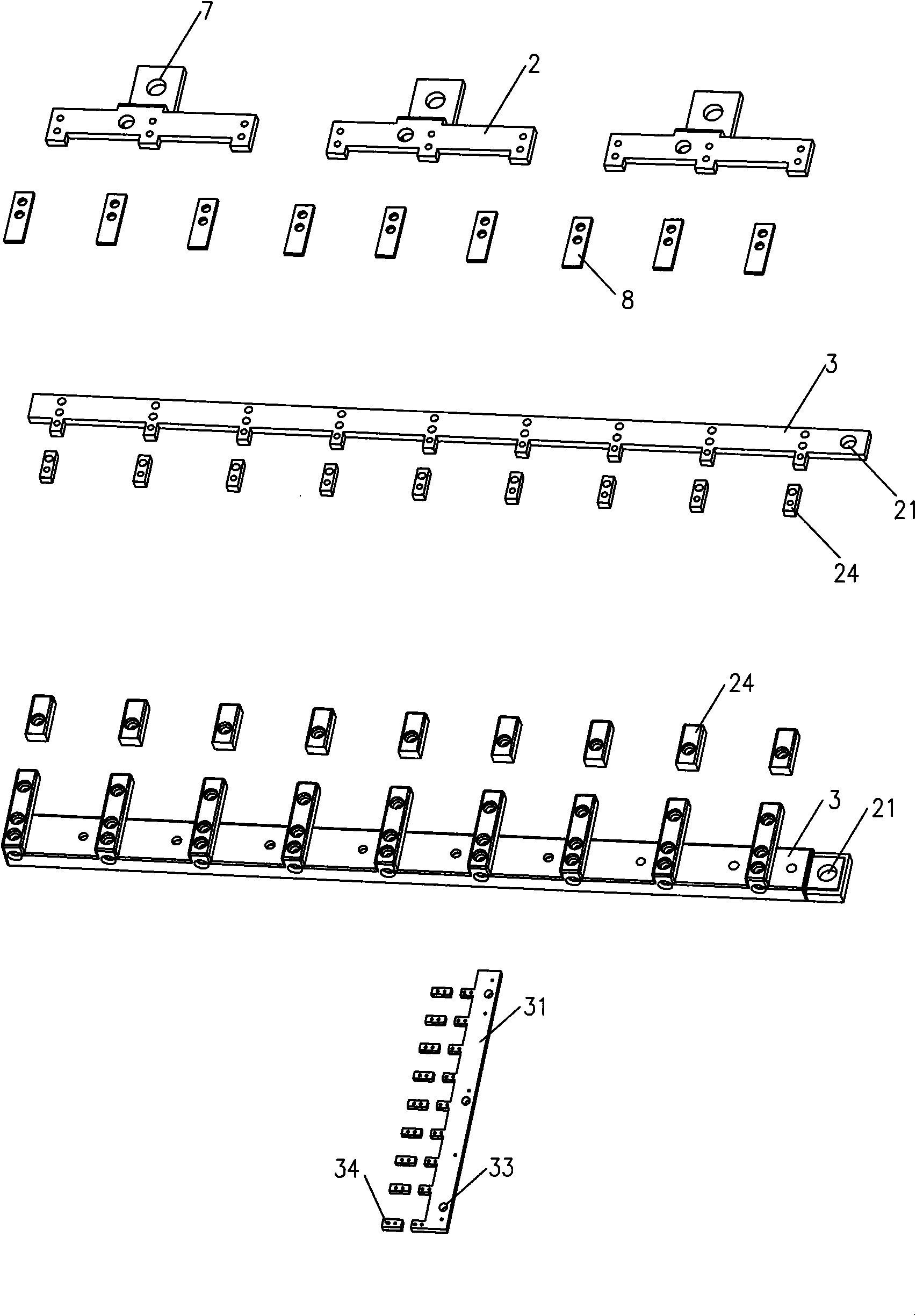
[0036] see figure 1 , an electric energy metering assembly structure provided by the present invention includes a base box 1. The present invention provides two types, which can also be a base plate 1. The two can be interchanged arbitrarily, and can also be other types with the same function; Electrical management device 35; the base box 1 is provided with a device for installing a meter.

[0037] The power consumption management device 35 is electrically connected to the meter installed on the substrate or the base box 1; the electrical connection is a serial port connection or a wire connection; the power consumption management device 35 can also be connected to the bottom plate of the box body 14 Movable connections, including fastening keys, screws or clips, etc., but the connection is inconvenie...


PUM


Abstract

The invention discloses a structure of electric energy metering assembly, which comprises a substrate or base box and an electricity utilization management device, wherein a meter mounting device is arranged on the substrate or base box; the electricity utilization management device is electrically connected with a meter arranged on the substrate or base box and moveably connected with the soleplate of a box body or the substrate or base box, and is a device having at least one of the functions of statistic, precharge, storage, monitoring, alarming, power cut and the like. The structure of electric energy metering assembly of the invention overcomes the disadvantages of the prior electricity meter box body, such as heavy weight, high cost, resource waste, inconvenient management and maintenance and the like, and has the advantages of assembly line work, resource saved, low cost, convenient assembly, simple structure, high commonality, convenient management and the like.

Description

technical field [0001] The invention relates to an electric energy metering assembly structure, in particular to an electric energy metering assembly structure used by multiple users. Background technique [0002] In order to facilitate the power consumption management of the power supply bureau, most of the power supply management departments now uniformly install and manage the electric energy meter boxes of a bungalow or a building or a floor. At present, most of the electric energy metering devices used by the electric power sector in the market are to install the electric energy meter and other metering devices separately in an independent meter box or install them in an independent meter box and then use other devices such as clamps to fix the single meter box. Assemble together; or install multiple electric energy meters in a large box structure, and then route them separately; if the date of authorization announcement is October 30, 2002, and the authorization announ...

Claims


Application Information

Patent Timeline
IPC IPC(8): G01R22/00G01R11/00
Inventor 万家盛
Owner 万叶琳
Learn More