A driving system for stage lighting optical components

A technology of optical components and driving systems, which is applied in the direction of electric light source, light source fixing, lighting device components, etc., can solve the problems of complicated installation, incompatibility, and influence on use, and achieve compact layout space, reduced occupied space, and reduced The effect of the amount used

Active Publication Date: 2018-11-16
GUANGZHOU HAOYANG ELECTRONICS CO LTD
View PDF7 Cites 0 Cited by
  • Summary
  • Abstract
  • Description
  • Claims
  • Application Information

AI Technical Summary

Problems solved by technology

The prior art usually adopts the structure of this kind of double prism to realize the composite effect of the multi-prism. Although each prism can swing in the optical axis plane and move in or out of the optical path, in the prior art, each prism is independent. A set of driving mechanism is used to move it in or out of the optical path, and the movement axes of each group of prisms are independent of each other and cannot be shared. A certain installation location and space, which increases the design difficulty in space design, requires rigorous space design for each component, otherwise interference is likely to occur, which will cause the use of each component to affect each other; and it needs to be equipped with Multiple motors and corresponding drive installation structures greatly increase the manufacturing cost of stage lighting to a certain extent, and the installation is complicated

Method used


Image

  • A driving system for stage lighting optical components
  • A driving system for stage lighting optical components
  • A driving system for stage lighting optical components

Examples


Embodiment 1

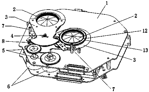
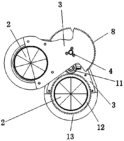
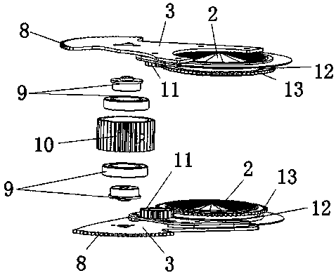
[0020] like Figure 1-3 As shown, a driving system for stage lighting optical components includes a support plate 1, two optical component brackets and two optical components (more optical component brackets and optical components can also be set as required), and the two optical components 2 are It is a prism, and each optical element 2 is correspondingly installed on an optical element bracket 3, and each optical element bracket 3 is rotatably sleeved on the rotating spindle 4 through a bearing assembly 9, and presents a staggered arrangement, and each optical element The brackets 3 are correspondingly connected to a group of driving mechanisms, the driving mechanisms are arranged on the support plate 1, and the support plate 1 is provided with a light-through hole for the light beam to pass through; and the end edge of each optical element bracket 3 is provided with its corresponding The drive mechanism engages the connected toothed structure 8 . Each set of driving mechan...

Embodiment 2

[0025] This embodiment is similar to Embodiment 1, the difference is that one of the two optical elements 2 is a prism, and the other is an atomizing mirror, and the prism is rotatably mounted on the corresponding optical element bracket 3, and the atomizing mirror It is non-rotatably installed on the corresponding optical element bracket 3; since the atomizing mirror does not need to rotate, the driven wheel 11 and the turntable 12 on the optical element bracket 3 for installing the atomizing mirror can be omitted in this embodiment. The working principle of this embodiment and the working principle of prism rotation are similar to those of Embodiment 1.

Embodiment 3

[0027] This embodiment is similar to Embodiment 1, the difference is that the two optical elements 2 are atomized mirrors, and the atomized mirrors are non-rotatably mounted on the corresponding optical element bracket 3; since the atomized mirrors do not need to rotate, Therefore, in this embodiment, the autorotation driving mechanism for driving the optical element 2 to autorotate can be omitted. The working principle of this embodiment is similar to Embodiment 1.


PUM


Abstract

A stage lighting optical component drive system comprises a support board (1), two or more optical component supports (3), and two or more optical components. Each of the optical components is correspondingly mounted on one of the optical component supports, and each of the optical component supports is correspondingly connected to a set of drive mechanism arranged on a support plate. A light passing hole is provided on the support plate and configured to pass a light beam. The drive system further comprises a rotating main shaft (4) on which the optical component supports are rotatably mounted and stacked in layers. A toothed structure (8) engaging with a corresponding drive mechanism is provided at an edge of an end portion of each of the optical component supports. The drive system is simple in structure and has a reasonable layout, reducing a space occupied in stage lighting equipment.

Description

technical field [0001] The invention relates to the technical field of stage lamps, and more particularly relates to a driving system for stage lamp optical components. Background technique [0002] In the field of stage lighting, in order to achieve a variety of gorgeous stage lighting effects, structures such as prisms, color chips, and gobos are usually set inside the stage lamps, and gorgeous light effects can be achieved through the combined use of prisms, color chips, and gobos . However, when a single prism is used, the lighting effect produced is relatively limited and the effect is relatively single. In order to solve this problem, two prisms are usually used in combination in actual use. For example, the Chinese utility model patent whose publication number is CN203868942U discloses a double prism combination for stage lamps. It is located above the light source and the light hole, and is located in the head of the lamp body of the stage lamp. The prior art usua...

Claims


Application Information

Patent Timeline
Patent Type & Authority Patents(China)
IPC IPC(8): F21S10/00F21V14/06F21V21/15F21W131/105F21W131/406
CPCF21S10/00F21V14/06F21V21/15
Inventor 蒋伟楷陈文峰
Owner GUANGZHOU HAOYANG ELECTRONICS CO LTD
Why Eureka
Try Eureka