Equipment monitoring system and method based on visible light communication

A technology for visible light communication and equipment monitoring, applied in short-range systems, material analysis by optical means, measurement devices, etc., can solve problems such as high cost, prone to negligence or omission, and achieve low cost and avoid negligence or omission. , the effect of large amount of information

Inactive Publication Date: 2015-12-02
WUHAN POST & TELECOMM RES INST CO LTD
View PDF7 Cites 9 Cited by
  • Summary
  • Abstract
  • Description
  • Claims
  • Application Information

AI Technical Summary

Problems solved by technology

LED display provides a direct way to transmit device information, but when there are multiple devices to be monitored or a large number of LED displays, because usually high-frequency (>50Hz) LED flicker cannot be detected by the naked eye, the complex information is beyond the human eye Processing power, difficult to perceive by the user's eyesight alone, prone to negligence or omission
However, to achieve perfect real-time monitoring through network management, it is necessary to add complex network management software and hardware facilities, and the cost is relatively high.

Method used


Image

  • Equipment monitoring system and method based on visible light communication
  • Equipment monitoring system and method based on visible light communication

Examples


Embodiment Construction

[0021] The present invention will be described in further detail below in conjunction with the accompanying drawings and embodiments.

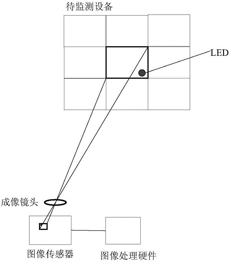
[0022] like figure 1 As shown, the device monitoring system based on visible light communication includes a monitoring device and multiple devices to be monitored. Each device to be monitored has at least one LED, and the position of each LED is fixed. Different information is represented by the color of the light and the flashing frequency. To reflect the status of the device to be monitored where it is located, the LED's light-emitting color and flashing frequency can also be controlled by coding to carry data information. The position and angle of the monitoring device relative to the device to be monitored are fixed, and the monitoring device includes an imaging lens, an image sensor, and image processing hardware. The imaging lens is used to photograph the LEDs on the equipment to be monitored. Since the monitoring equipment can photogra...


PUM


Abstract

The invention relates to the field of LED display and image sensors, and particularly relates to an equipment monitoring system based on visible light communication. The equipment monitoring system comprises multiple pieces of equipment to be monitored, wherein each piece of equipment to be monitored is at least provided with one LED. The equipment monitoring system also comprises monitoring equipment, wherein the position and angle of the monitoring equipment relative to the equipment to be monitored are fixed, the monitoring equipment comprises an imaging lens, an image sensor and image processing hardware, the imaging lens is used for shooting the LED on the equipment to be monitored, the image sensor is used for imaging a picture shot by the imaging lens, and the image processing hardware is used for identifying the state of the equipment to be monitored on which the LED is positioned according to the position, emitting light color and flicker frequency of the LED. The equipment monitoring system provided by the invention achieves a network management function, as well as concentrated recording and monitoring of a large quantity of equipment to be monitored, avoids negligence or omission, and is simple and low in cost.

Description

technical field [0001] The invention relates to the field of LED displays and image sensors, in particular to an equipment monitoring system and method based on visible light communication. Background technique [0002] LED (Lighting Emitting Diode, light-emitting diode) is called the fourth-generation lighting source or green light source, and has been widely used for indication and lighting. Because LED has good modulation characteristics as a light source, it can also be used for lighting and can also load signals to realize wireless optical communication, so it is also used to realize a series of communication applications. [0003] LEDs are usually used on the panels of digital devices to indicate device information, and different information is transmitted to users through different LEDs, different colors, and different flashing frequencies. LED display provides a direct way to transmit device information, but when there are multiple devices to be monitored or a large...

Claims


Application Information

Patent Timeline
IPC IPC(8): G01N21/84H04B10/116
Inventor 刘武杨超杨奇
Owner WUHAN POST & TELECOMM RES INST CO LTD
Why Eureka
Try Eureka