Improved fitting jig of touch liquid crystal module

A technology for liquid crystal modules and bonding fixtures, which is applied in the input/output process of data processing, optics, instruments, etc., and can solve the problems of low bonding efficiency, multiple assembly tolerances, and inaccurate bonding efficiency, etc.

Active Publication Date: 2015-12-02
INTERFACE OPTOELECTRONICS SHENZHEN +1
View PDF5 Cites 6 Cited by
  • Summary
  • Abstract
  • Description
  • Claims
  • Application Information

AI Technical Summary

Problems solved by technology

[0005] Among them, a previous Chinese patent publication number: CN203496401U, the patent name "touch screen bonding fixture" discloses a touch screen bonding fixture, discloses a touch screen bonding fixture, which is to improve the traditional A joint fixture with low technical bonding efficiency. The previous proposal includes a cuboid panel with a groove. The cross section of the groove is rectangular. The bottom surface is parallel, and there is a limiting part on the cuboid panel, which is close to a corner of the groove
The technical effect of the previous case is different from the traditional technology of the film fixture. In actual application, because the size of the groove matches the size of the touch module, the liquid crystal module needs to be placed after matching the groove more accurately. The bonding efficiency of the traditional bonding fixture has been improved, but the bonding efficiency is still not accurate enough after the improvement. Although the limit part can quickly position the LCD module and the touch module, and the convex strip can block the liquid crystal Module, but relying only on the fixing of one side of the limit part, it will still require more assembly tolerances when the touch module and the liquid crystal module are joined, and it is still impossible to join more accurately

Method used


Image

  • Improved fitting jig of touch liquid crystal module
  • Improved fitting jig of touch liquid crystal module
  • Improved fitting jig of touch liquid crystal module

Examples


Embodiment Construction

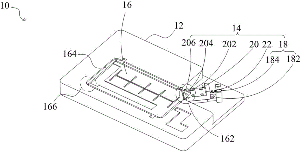
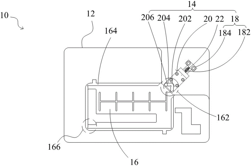
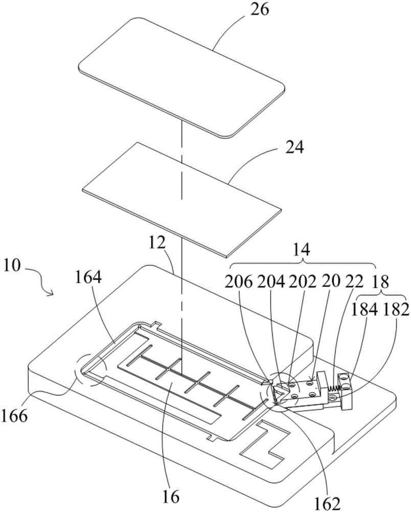
[0047] With the demand for narrow borders of electronic products in the electronic product market, more and more touch LCD modules require assembly accuracy to change from the visible area (ViewableArea, V / A) to the active area (ActiveArea, A / A) to Touch panel edge alignment (TouchPanelEdge) to LCD module edge alignment (LCDModuleEdge), and improve control accuracy from 0.3mm to 0.2mm to reduce assembly risk. At the same time, the cost reduction requirements of electronic products are applied, so that more models begin to switch from full-plane bonding (DirectBond) to word-of-mouth bonding or frame bonding (AirBond) to reduce material costs. Under this condition, most hardware The production requirements of such products are no longer applicable to Hard-To-Hard (HTH) machines. Because, the HTH machine’s photosensitive couple and components (ChargeCoupledDevice, CCD) capture V / A and A / A, changing to side-by-side alignment requires a large amount of machine modification costs, a...


PUM


Abstract

The invention discloses an improved fitting jig of a touch liquid crystal module. The improved fitting jig can provide a touch module and a liquid crystal module which are assembled. The improved fitting jig comprises a base with a groove and a positioning apparatus, wherein an opening part is formed in one corner of the groove of the base; the groove can accommodate the touch module and the liquid crystal module; and the positioning apparatus is positioned in the opening part of the base and can fix the touch module and the liquid crystal module in the groove of the base. According to the improved fitting jig, the module-to-module assembly precision of the touch module and the liquid crystal module in the jig can be improved through the positioning apparatus to meet the edge-to-edge 0.2mm assembly tolerance demand of a user on products, and meanwhile, the improved fitting jig of the touch liquid crystal module can greatly reduce the cost of assembly materials to satisfy low-cost manufacturing policies of electronic products nowadays.

Description

technical field [0001] The invention relates to a production auxiliary tool for a liquid crystal module and a touch module assembled into a touch liquid crystal module, in particular to a touch liquid crystal module that uses a positioning device to fix the liquid crystal module and the touch module Group of improved fitting fixtures. Background technique [0002] With the explosive improvement of 3C industry technology, portable mobile devices such as mobile phones, personal digital assistants, notebook computers and tablet computers in the past are all developing in the direction of convenience, technology diversification and appearance beautification. However, the display screens in the above-mentioned various portable mobile devices have progressed from the display function in the past to the function of touch operation, and most of the display screens are liquid crystal displays (Liquid Crystal Display, LCD) as the mainstream, and the input method has also changed from ...

Claims


Application Information

Patent Timeline
Patent Type & Authority Applications(China)
IPC IPC(8): G06F3/041G02F1/13G02F1/1333
Inventor 谢冬生
Owner INTERFACE OPTOELECTRONICS SHENZHEN
Why Eureka
Try Eureka