Rotor end ring

A rotor end ring and rotor technology, applied in the direction of magnetic circuit rotating parts, magnetic circuit shape/style/structure, etc., can solve the problems of rotor end ring wear, hidden dangers, large space occupied by cooling fans, etc., and achieve good heat dissipation. Effect

Inactive Publication Date: 2015-12-02
天津鑫汇天通科技有限公司
View PDF0 Cites 0 Cited by
  • Summary
  • Abstract
  • Description
  • Claims
  • Application Information

AI Technical Summary

Problems solved by technology

During the working process, it is often necessary to connect a cooling fan on one side of the rotor end ring, while the conventional cooling fan not only occupies a large space, but also easily wears out with the rotor end ring during the working process, resulting in damage to the fan; in addition, the rotor end ring The fixation with the rotor often depends on driving the aluminum guide bar into the groove on the rotor, which also has certain potential safety hazards

Method used


Image

  • Rotor end ring
  • Rotor end ring

Examples


Embodiment Construction

[0018] In order to make the content of the present invention more clearly understood, the present invention will be further described in detail below based on specific embodiments.

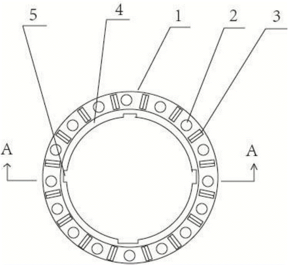
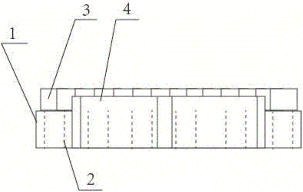
[0019] Such as figure 1 , 2 As shown, a rotor end ring includes a circular ring 1, the material of which is copper, and a plurality of circular through holes 2 are arranged on the circular ring 1, and the through holes 2 are evenly distributed on the circular ring 1. On the surface of the ring 1, the surface of the ring 1 between the adjacent through holes 2 is provided with rotor blades 3, the rotor blades 3 are in the shape of a three-sided column, and the quadrilateral surface of the three-sided column-shaped rotor blade 3 is welded Located on the surface of the circular ring 1, the circular ring 1 is located on the inner peripheral side and is provided with an outwardly protruding circular platform 4, and the circular platform 4 is arranged on any side of the circular ring 1. The circular rin...


PUM


Abstract

The present invention relates to a rotor end ring including a circular ring. The rotor end ring is characterized in that: the circular ring is provided with a plurality of circular through holes, the surface of the circular ring between two adjacent through holes is provided with a rotor fan blade respectively, the rotor fan blade is triangular prism shaped, the interior circumference of the circular ring is provided with a circular platform raised outwards, and the circular ring and the inner surface of the circular platform are provided with recessed rotor clamping grooves evenly. The rotor fan blade of the rotor end ring can achieve a better heat dissipation effect when the rotor turns, the circular ring is convenient to fix the rotor end ring, and the recessed rotor clamping grooves enable the rotor end ring to preferably cooperate with the rotor for working.

Description

technical field [0001] The invention relates to the field of motor manufacturing, in particular to a rotor end ring. Background technique [0002] The cast aluminum rotor of the motor is generally composed of rotor core, guide bar and end ring. The aluminum guide bar is driven into the groove on the rotor, and the rotor core is exposed at both ends. The two ends of the aluminum guide bar are respectively cast and connected with cast aluminum end ring. During the working process, it is often necessary to connect a cooling fan on one side of the rotor end ring, while the conventional cooling fan not only occupies a large space, but also easily wears out with the rotor end ring during the working process, causing damage to the fan; in addition, the rotor end ring The fixation with the rotor often depends on driving the aluminum guide bar into the groove on the rotor, which also has certain potential safety hazards. [0003] Therefore, based on these problems, it is of great p...

Claims


Application Information

Patent Timeline
Patent Type & Authority Applications(China)
IPC IPC(8): H02K1/22
Inventor 关士奇
Owner 天津鑫汇天通科技有限公司
Why Eureka
Try Eureka