
Photovoltaic assembly installation support and roof photovoltaic system

A technology of photovoltaic modules and mounting brackets, which is applied to the supporting structure of photovoltaic modules, photovoltaic power generation, photovoltaic modules, etc., can solve the problems of complex installation, heavy roof load, and high cost, and achieve simple installation process, convenient fixing method, and overall The effect of cost reduction

Inactive Publication Date: 2015-12-02
湖南俊虹置业股份有限公司
View PDF9 Cites 8 Cited by
  • Summary
  • Abstract
  • Description
  • Claims
  • Application Information

AI Technical Summary

Problems solved by technology

Existing rooftop photovoltaic systems are difficult to promote due to the following problems: Most existing rooftop photovoltaic systems use framed photovoltaic modules (although framed photovoltaic modules are much heavier than frameless photovoltaic modules and cost less It is also much higher, but frameless photovoltaic modules are rarely used in rooftop photovoltaic systems due to inconvenient fixation and complicated installation). The above-mentioned photovoltaic modules with frames are fixed on the roof beams through brackets, while photovoltaic Due to its heavy weight, it will directly lead to a large load on the roof. In order to ensure the safety and stability and reliability of the photovoltaic system, the building needs to have strong load rigidity and high bearing capacity. Therefore, the existing roof Photovoltaic systems are not only expensive but also have high requirements for buildings

Method used


Image

  • Photovoltaic assembly installation support and roof photovoltaic system
  • Photovoltaic assembly installation support and roof photovoltaic system
  • Photovoltaic assembly installation support and roof photovoltaic system

Examples


Embodiment Construction

[0040] In order to facilitate the understanding of those skilled in the art, the present invention will be further described below in conjunction with the embodiments and accompanying drawings, and the contents mentioned in the embodiments are not intended to limit the present invention.

[0041] In describing the present invention, it should be understood that the terms "center", "longitudinal", "transverse", "length", "width", "thickness", "upper", "lower", "front", " Orientation indicated by rear, left, right, vertical, horizontal, top, bottom, inside, outside, clockwise, counterclockwise, etc. The positional relationship is based on the orientation or positional relationship shown in the drawings, which is only for the convenience of describing the present invention and simplifying the description, rather than indicating or implying that the referred device or element must have a specific orientation, be constructed and operated in a specific orientation, Therefore, it sho...


PUM


Abstract

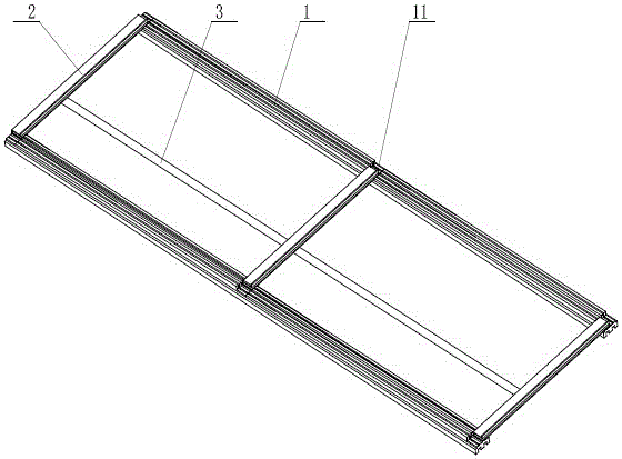
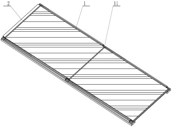
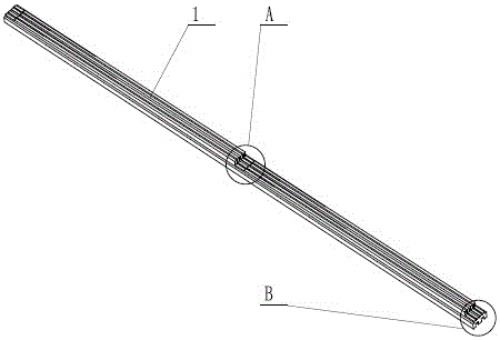
The invention provides a photovoltaic assembly installation support and a roof photovoltaic system comprising the same, relating to the photovoltaic generating technology field. The photovoltaic assembly installation support comprises No.1 support rods, and No.2 support rods; the No.2 support rods are arranged between the No.1 support rods and are crossing with the No.1 support rods in a perpendicular manner; the No.2 support rod comprises a support rod main body with an insertion groove in the middle and a baffle arranged on the upper surface of the support rod main body; the cross section of the support rod main body is of an U shape; the tops of the No.1 support rods are provided with positioning grooves for bearing and positioning the No.2 support rods; the height of the left side wall of the positioning groove is equal to that of the support rod main body; the height of the right side wall is equal to that from the lower surface of the support rod main body to the lower surface of the insertion groove; the top of the No.1 support rod is provided with a glue injection groove which is arranged along the length direction of the No.1 support rod. The roof photovoltaic system comprises a photovoltaic assembly installation support, a frameless photovoltaic assembly and a roof crossbeam; the frameless photovoltaic assembly is installed on the photovoltaic assembly installation support which is fixed on the roof crossbeam.

Description

technical field [0001] The invention relates to the technical field of photovoltaic power generation, in particular to a photovoltaic module installation bracket and a roof photovoltaic system. Background technique [0002] Among all kinds of renewable energy, solar energy covers a wide area and is an inexhaustible clean energy. Solar photovoltaic power generation technology is currently the fastest-growing and most cutting-edge research field in the field of solar energy utilization. [0003] In recent years, many photovoltaic power plants have been built in various parts of our country. The photovoltaic power generation system usually includes two types: roof photovoltaic system and ground photovoltaic system. Existing rooftop photovoltaic systems are difficult to promote due to the following problems: Most existing rooftop photovoltaic systems use framed photovoltaic modules (although framed photovoltaic modules are much heavier than frameless photovoltaic modules and cos...

Claims


Application Information

Patent Timeline
IPC IPC(8): H02S20/23
CPCY02B10/10Y02E10/50
Inventor 刘俊健康淑红
Owner 湖南俊虹置业股份有限公司
Learn More