Carbon fiber wire and method of processing and connecting the carbon fiber wire and metal line joint

A technology of carbon fiber wire and connection method, applied in the direction of heating element, heating element material, heating element shape, etc., can solve the problems of uncontrollable power and heat, poor connection, performance impact, etc., and achieve easy control of power and heat, joints There is no special increase in temperature, and the effect of avoiding high temperature and even ablation

Active Publication Date: 2015-12-02
SHANDONG YINGHAO ELECTRONICS TECH CO LTD
View PDF7 Cites 6 Cited by
  • Summary
  • Abstract
  • Description
  • Claims
  • Application Information

AI Technical Summary

Problems solved by technology

When used, the carbon fiber wire needs to be connected with the metal wire to connect the circuit. In practice, because the first high temperature resistant protective layer of the existing carbon fiber wire is too thin, 99% of the carbon fiber wire is peeled after peeling during a rotary cut. The carbon fiber filaments will be damaged and broken around the filaments. Sometimes the carbon fiber filaments are damaged by more than 5%, and the resistance increases, which greatly changes the basic design power of the product, resulting in the inability...

Method used


Image

  • Carbon fiber wire and method of processing and connecting the carbon fiber wire and metal line joint

Examples


Embodiment 1

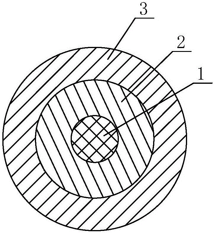
[0027] Such as figure 1 As shown, a carbon fiber thread includes a carbon fiber filament 1, a first high temperature resistant protective layer 2 is provided outside the carbon fiber filament 1, a second high temperature resistant protective layer 3 is provided outside the first high temperature resistant protective layer 2, and the first high temperature resistant protective layer 3 is provided outside the first high temperature resistant protective layer 2. The wall thickness of the first high temperature resistant protective layer 2 is 2-3 mm, which changes the situation that the first high temperature resistant protective layer of the existing carbon fiber wire is too thin, avoids the damage to the internal carbon fiber wire when the carbon fiber wire is rotary cut and peeled, and ensures The basic design power of the product remains unchanged, and it is easy to control power and heat during later use.

[0028] Both the first high temperature resistant protective layer 2 a...

Embodiment 2

[0039] Such as figure 1 As shown, a carbon fiber thread includes a carbon fiber filament 1, a first high temperature resistant protective layer 2 is provided outside the carbon fiber filament 1, a second high temperature resistant protective layer 3 is provided outside the first high temperature resistant protective layer 2, and the first high temperature resistant protective layer 3 is provided outside the first high temperature resistant protective layer 2. The wall thickness of the first high temperature resistant protective layer 2 is 2-3 mm, which changes the situation that the first high temperature resistant protective layer of the existing carbon fiber wire is too thin, avoids the damage to the internal carbon fiber wire when the carbon fiber wire is rotary cut and peeled, and ensures The basic design power of the product remains unchanged, and it is easy to control power and heat during later use.

[0040] Both the first high temperature resistant protective layer 2 a...


PUM

PropertyMeasurementUnit
Wall thicknessaaaaaaaaaa

Abstract

A carbon fiber wire comprises carbon fiber yarns. A first high temperature resistance protecting layer is arranged on the outer side of the carbon fiber yarns. A second high temperature resistance protecting layer is arranged on the outer side of the first high temperature resistance protecting layer. The wall thickness of the first high temperature resistance protecting layer ranges from 2 mm to 3 mm. The carbon fiber wire with a reasonable structure is simple to operate. The internal carbon fiber yarns are prevented from being damaged during a carbon fiber wire rotary-cut peeling process. The basic design power of a product is unchanged. The power and heat can be easily controlled during later-stage using processes. Furthermore, the carbon fiber yarns and metal line joints are tightly and firmly connected. Reliable performance is achieved. No special joint temperature rise emerges. High-temperature or even ablation phenomena caused by virtual connection can be prevented. The carbon fiber wire is safe and reliable.

Description

Technical field: [0001] The invention relates to a carbon fiber wire and a method for processing and connecting the joint with a metal wire. Background technique: [0002] At present, carbon fiber wire is used as a heating element, and can be used to make any heating products, which is very popular among users. When used, the carbon fiber wire needs to be connected with the metal wire to connect the circuit. In practice, because the first high temperature resistant protective layer of the existing carbon fiber wire is too thin, 99% of the carbon fiber wire is peeled after peeling during a rotary cut. The carbon fiber filaments will be damaged and broken around the filaments. Sometimes the carbon fiber filaments are damaged by more than 5%, and the resistance increases, which greatly changes the basic design power of the product, resulting in the inability to control power and heat during later use. In addition, carbon fiber wires and metal wire joints are usually directly c...

Claims


Application Information

Patent Timeline
IPC IPC(8): H05B3/56H05B3/10H05B3/08
Inventor 吴俊岩
Owner SHANDONG YINGHAO ELECTRONICS TECH CO LTD
Why Eureka
Try Eureka