Liquid elastomer molding method

An elastomeric, liquid-like technology

Active Publication Date: 2015-12-02
NOK CORP
View PDF7 Cites 2 Cited by
  • Summary
  • Abstract
  • Description
  • Claims
  • Application Information

AI Technical Summary

Problems solved by technology

With regard to gaskets, the amount of discarded molding material (liquid elastomer) can be reduced by using injection molding. If it is on a plane (orthogonal to the mold clamping and opening direction), the mold will become larger and the manufacturing efficiency will be poor.
[0003] In addition, although the following patent document 1 discloses a technique for simultaneously molding a plurality of molded products using a die, this prior art is not injection molding but a molding machine for compression molding

Method used


Image

  • Liquid elastomer molding method
  • Liquid elastomer molding method
  • Liquid elastomer molding method

Examples


no. 1 example ·

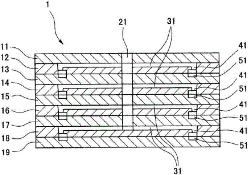
[0053] First embodiment...

[0054] figure 1 as well as figure 2 A cross-section of the die 1 used for implementing the forming method according to the first embodiment of the present invention is shown. The mold 1 is a mold for injection molding, and a plurality (four in this embodiment) of the same shape and size are arranged side by side at predetermined intervals in the mold clamping and opening direction (the up-and-down direction in the figure) of the mold 1 . In the product cavity space 51, a plurality of (four in this embodiment) molded products 101 of the same shape and size can be formed simultaneously by using the mold 1 . In addition, the mold 1 includes nine split molds 11 to 19, which are stacked and arranged in a mold clamping and opening direction of the mold 1. Among them, except for the first mold 11 provided with a sprue opening, In the mold parting part of the second mold 12 and the third mold 13, the mold parting part of the fourth mold 14 and the fift...

no. 2 example ·

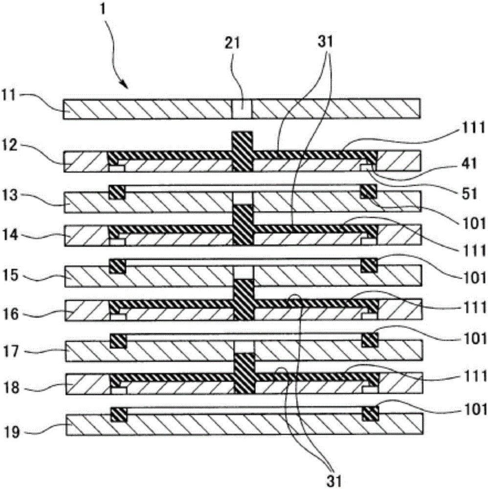
[0059] Second embodiment...

[0060] image 3 as well as Figure 4 A cross-section of the mold 1 used for implementing the forming method according to the second embodiment of the present invention is shown. The mold 1 is a mold for injection molding, and a plurality (five in this embodiment) of the same shape and size are arranged side by side at predetermined intervals in the mold clamping and opening direction (the up-and-down direction in the figure) of the mold 1. The product cavity space 51 can simultaneously form a plurality of (five in this embodiment) molded products 101 of the same shape and size by using the mold 1 . In addition, the mold 1 includes eight split molds 11 to 18, which are stacked and arranged in the mold clamping and mold opening direction of the mold 1. Among them, except for the first to eighth split molds 11 to 18 provided with the injection port 21 and the orthogonal channel portion 32, In addition to the first mold 11 and the second mold 12, i...

no. 3 example ·

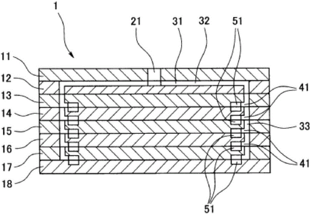
[0068] The third embodiment...

[0069] Figure 5 as well as Image 6 A cross-section of the mold 1 used for implementing the molding method according to the third embodiment of the present invention is shown. The mold 1 is a mold for injection molding, and a plurality (five in this embodiment) of the same shape and size are arranged side by side at predetermined intervals in the mold clamping and opening direction (the up-and-down direction in the figure) of the mold 1. The product cavity space 51 can simultaneously form a plurality of (five in this embodiment) molded products 101 of the same shape and size by using the mold 1 . In addition, the mold 1 includes eight split molds 11 to 18, which are stacked and arranged in the mold clamping and mold opening direction of the mold 1. Among them, except for the first to eighth split molds 11 to 18 provided with the injection port 21 and the orthogonal channel portion 32, In addition to the first mold 11 and the second mold 12,...


PUM


Abstract

In order to provide a liquid elastomer molding method which enables a reduction in the volume of discarded molding material and, moreover, does not involve an increase in the planar size of a mold when using the mold to simultaneously mold a plurality of molded articles and thus has excellent production efficiency, this method uses a mold to mold a molded article comprising a liquid elastomer, the mold (1) being an injection molding mold, with a plurality of product cavity spaces (51) being provided in a line in the clamping and opening direction of the mold and a plurality of molded articles being molded simultaneously using the mold. The mold is provided with a sprue (21), runners (31), and gates (41) which lead to the plurality of product cavity spaces, and the runners are provided with perpendicular runner sections (32) extending from the sprue in a direction perpendicular to the clamping and opening direction of the mold and parallel runner sections (33) extending from the perpendicular runner sections in a direction parallel to the clamping and opening direction of the mold, the parallel runner sections being disposed on the outer side of the plurality of product cavity spaces.

Description

technical field [0001] The present invention relates to a method for molding a liquid elastic body, and more specifically, to a method for molding a molded article made of a liquid elastic body using a mold. Molded articles made of liquid elastomers are, for example, fuel cell gaskets or other general gaskets or gaskets. Background technique [0002] For the spread of fuel cells in the future, it is necessary to reduce the size and cost of separators, gaskets, and the like. With regard to gaskets, the amount of discarded molding material (liquid elastomer) can be reduced by using injection molding. On a flat surface (the direction perpendicular to the clamping and opening direction of the mold), the mold will become larger and the manufacturing efficiency will be poor. [0003] In addition, although the following Patent Document 1 discloses a technique for simultaneously molding a plurality of molded products using a die, this prior art is not injection molding but a moldi...

Claims


Application Information

Patent Timeline
Patent Type & Authority Applications(China)
IPC IPC(8): B29C45/32B29C45/14B29L31/26
CPCB29C45/32B29C45/322B29K2021/006B29L2031/265B29C33/0066B29C33/0088B29C45/14336B29C2045/2712B29L2031/3468H01M8/0284H01M8/0286Y02E60/50Y02P70/50
Inventor 古贺正太郎
Owner NOK CORP
Why Eureka
Try Eureka