
Sound attenuating structures

A sound wave, panel technology, applied in the field of novel sound-absorbing structures

Active Publication Date: 2015-12-02
THE HONG KONG UNIV OF SCI & TECH
View PDF8 Cites 30 Cited by
  • Summary
  • Abstract
  • Description
  • Claims
  • Application Information

AI Technical Summary

Problems solved by technology

This is disadvantageous for noise blocking applications that also require ventilation

Method used


Image

  • Sound attenuating structures
  • Sound attenuating structures
  • Sound attenuating structures

Examples


Embodiment

[0098] Figure 11A icon Figure 11B Absorption properties of the unit shown in . exist Figure 11A In , curve 111 represents the measured absorption coefficient of sample 5. There are three absorption peaks at 172, 340, and 813 Hz, marked with arrows at the abscissa along the bottom of the graph. Arrows at 172, 340, and 710 Hz indicate the positions of the absorption peak frequencies obtained from finite element simulations. The 813 Hz peak is the observed peak position from the experimental results appearing at curve 111 "D". The arrow at 710 Hz indicates the theoretical peak position obtained by numerical calculation. Ideally the two values ​​710 Hz and 813 Hz would have been the same, so this difference indicates that the theoretical calculation is not a completely accurate prediction for sample 5 due to modeling the physical properties of the sample.

[0099] Figure 11A The unit consists of a rectangular elastic membrane with a length of 31 mm, a width of 15 mm, an...


PUM

PropertyMeasurementUnit
Thicknessaaaaaaaaaa
Radiusaaaaaaaaaa
Radiusaaaaaaaaaa

Abstract

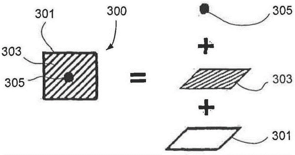
A sound attenuation panel is configured with a substantially acoustically transparent planar, rigid frame divided into a plurality of individual, substantially two-dimensional cells. A sheet of a flexible material is fixed to the rigid frame, and a plurality of platelets fixed to the sheet of flexible material such that each individual cell of the plurality of cells is provided with a respective platelet to establish a resonant frequency, the resonant frequency defined by the planar geometry of the individual cells, the flexibility of the flexible material and the platelets. The cells are divided into at least two different types of the individual cells, configured so that sound waves emitted by a first type of said different types of individual cells establishes a sound cancellation pattern with sound waves emitted by a second type of said different individual cells or an aggregation of different types of the individual cells.

Description

technical field [0001] The invention relates to a novel sound-absorbing structure, in particular to a local resonance acoustic material (LRSM). Locally resonant acoustic materials provide shielding or acoustic barriers for specific frequency ranges and can be layered to act as broadband anechoic barriers. Background technique [0002] In recent years, a new class of acoustic materials has been discovered, based on the principle of constructing localized resonances. This material breaks the mass-density law of sound attenuation, which states that in order to attenuate sound transmission to the same degree, the thickness, or mass per unit area, of a solid panel must vary inversely with the sound frequency. Therefore, with conventional sound deadening materials, low frequency sound deadening may require very thick solid panels, or panels made of a material with a high density such as lead. [0003] The fundamentals of this new class of materials, Locally Resonant Acoustic Mat...

Claims


Application Information

Patent Timeline
IPC IPC(8): G10K11/16G10K11/172
CPCG10K11/172G10K11/175
Inventor 杨志宇沈平马冠聪杨旻李勇
Owner THE HONG KONG UNIV OF SCI & TECH
Learn More