Dual waste scrap treatment device for numerically controlled lathe

A technology of CNC lathes and processors, applied in metal processing machinery parts, maintenance and safety accessories, metal processing equipment, etc., can solve the problems of flying waste, stuck and unable to open, unable to remove waste well, etc. , to achieve the effect of comprehensive cleaning function

Active Publication Date: 2015-12-09
ZHEJIANG JINTANG MACHINE TOOL
View PDF10 Cites 9 Cited by
  • Summary
  • Abstract
  • Description
  • Claims
  • Application Information

AI Technical Summary

Problems solved by technology

[0003] However, the double waste processor of the existing CNC lathe is to fix the required car parts on the turntable through the fixture, drive the parts to rotate at high speed through the turntable, and then slide slowly on the slide rail through the turning tool. The turning table is close to the turntable, and finally the turning tool is in contact with the parts, so that the required parts can be effectively turned out. Since the turntable rotates at a high speed during the turning process, the waste chips generated will fly randomly, and some of them will be attached to the CNC lathe. On the inner wall of the double waste processor rack shell, the mobile door on the rack shell is stuck and cannot be opened or closed during operation, while the existing chip removal mechanism can only passively wait for the waste to fall to the On the chip flute, it is not possible to remove the waste attached to the inner wall of the rack shell well

Method used


Image

  • Dual waste scrap treatment device for numerically controlled lathe
  • Dual waste scrap treatment device for numerically controlled lathe
  • Dual waste scrap treatment device for numerically controlled lathe

Examples


Embodiment Construction

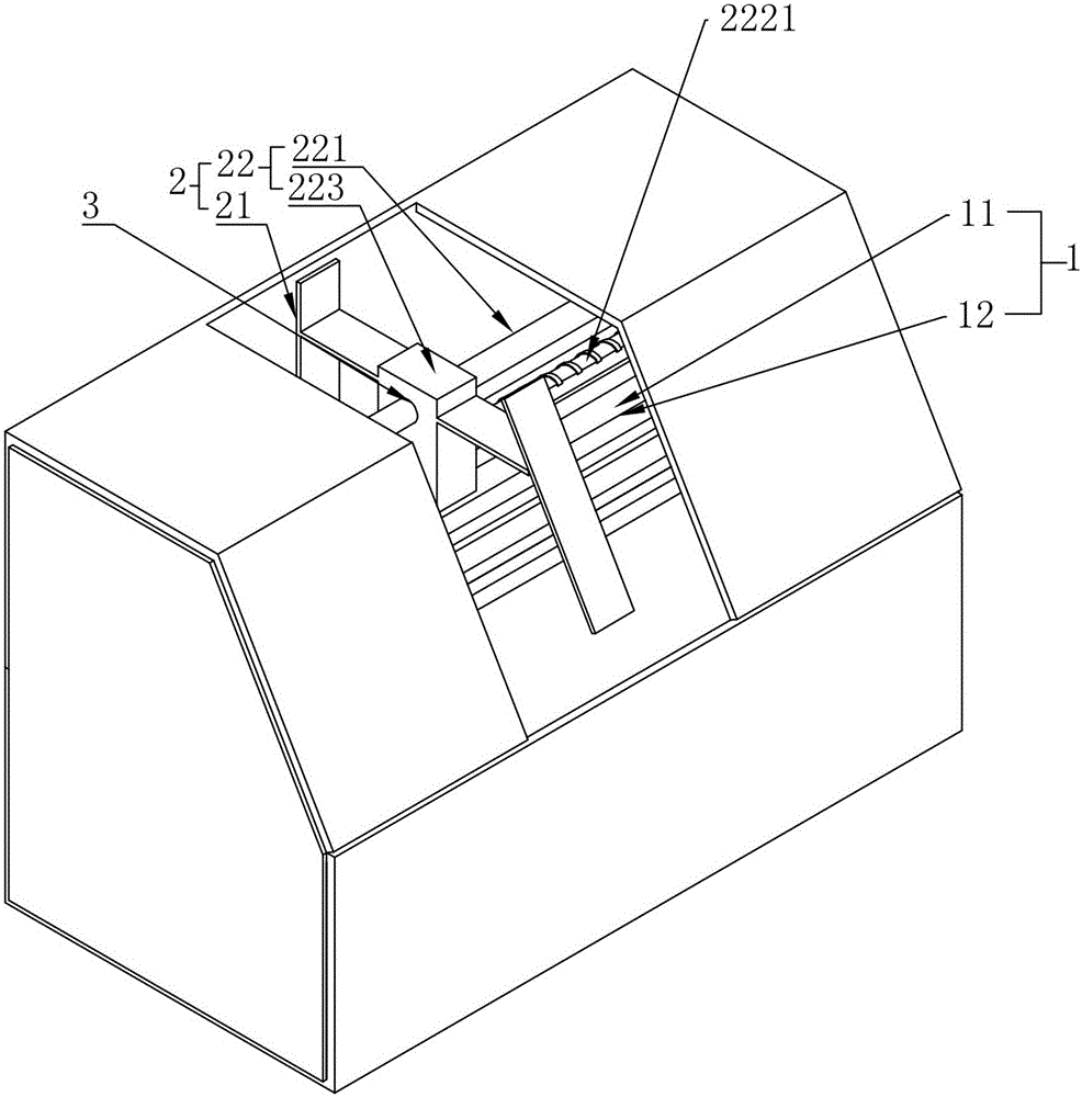
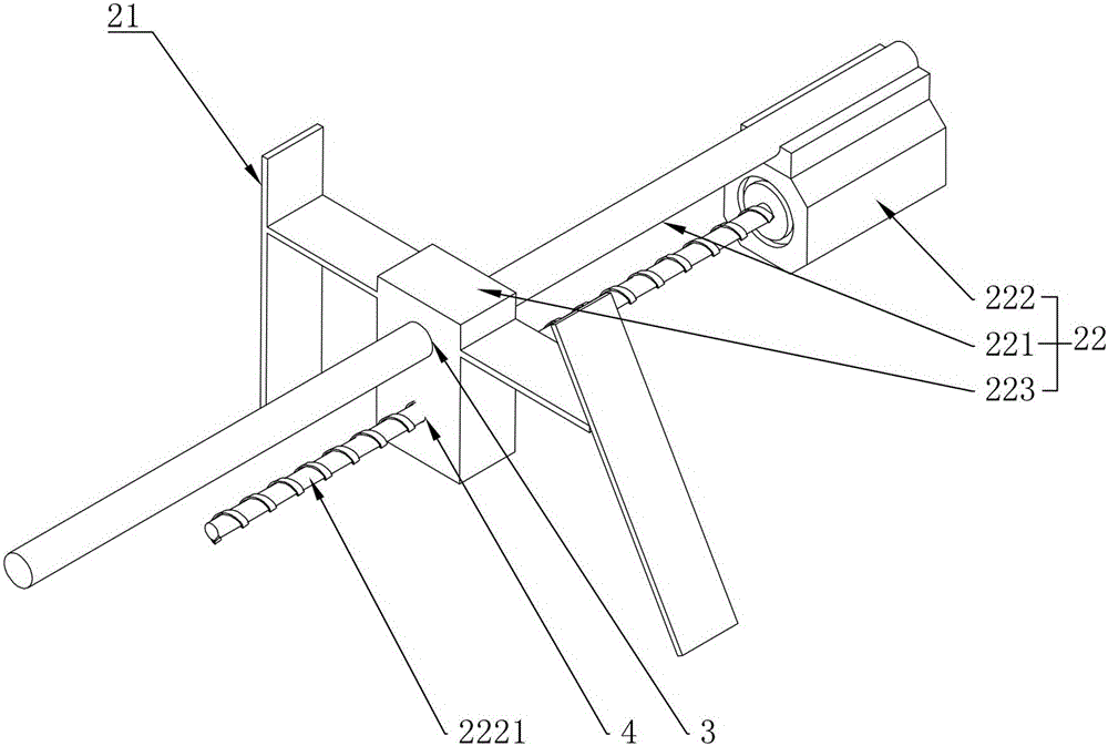
[0014] refer to Figures 1 to 4As shown, a double waste processor for a CNC lathe in this embodiment includes a bottom chip removal mechanism 1 and a side wall chip removal mechanism 2, and the bottom chip removal mechanism 1 includes a double waste chip that sends waste chips out of the CNC lathe The conveyor belt 11 of the processor and the chip discharge groove 12 for receiving waste chips, the conveyor belt 11 is used as the groove bottom of the chip discharge groove 12, the side wall chip removal mechanism 2 is arranged above the chip discharge groove 12, and the side wall The wall chip removal mechanism 2 includes a scraper 21 attached to the casing of the CNC lathe frame and a drive assembly 22 that drives the scraper 21 to move back and forth. Shaft 221, a driving motor 222 fixed on one end of the fixed shaft 221, and a slider 223 sliding on the fixed shaft 221, the slider 223 is fixed with the scraper 21, and a screw is coaxially fixed on the rotating shaft of the dri...


PUM


Abstract

The invention discloses a dual waste scrap treatment device for a numerically controlled lathe. The dual waste scrap treatment device comprises a bottom scrap discharge device and a side wall scrap discharge device, wherein the bottom scrap discharge device comprises a conveying belt of the dual waste scrap treatment device, which is used for discharging waste scrap out of the dual waste scrap treatment device and a scrap discharge groove used for accommodating waste scraps; the conveying belt is used as a groove bottom of the scrap discharge groove; the side wall scrap discharge device is arranged above the scrap discharge groove and comprises a scrapping plate fitted with a rack housing of the numerically controlled lathe and a driving component used for driving the scrapping plate to move back and forth. According to the dual waste scrap treatment device disclosed by the invention, by arranging the driving component, the scrapping plate is effectively driven to move back and forth in the rack housing, so that the inner wall of the rack housing can be effectively cleaned.

Description

technical field [0001] The invention relates to a numerical control device, more specifically to a double waste processor for a numerical control lathe. Background technique [0002] The double waste processor of the CNC lathe will produce a lot of waste when turning various workpieces. In order to ensure the normal operation of the lathe, the double waste processor of the CNC lathe needs to be equipped with a chip removal mechanism. The generated waste chips are discharged in a timely manner. The structure of the existing chip removal mechanism generally includes a chip removal groove and a conveyor belt arranged at the bottom of the chip removal groove. During the chip removal process, the generated waste chips It will fall into the chip flute, and then the waste chips can be effectively discharged from the double waste processor of the CNC lathe through the operation of the conveyor belt. [0003] However, in the working process of the double waste processor of the exist...

Claims


Application Information

Patent Timeline
Patent Type & Authority Applications(China)
IPC IPC(8): B23Q11/00
CPCB23Q11/0067
Inventor 丁晓伟陈戌连
Owner ZHEJIANG JINTANG MACHINE TOOL
Why Eureka
Try Eureka