A biochemical pool water distribution system

A technology of distribution system and biochemical pool, which is applied in the field of sewage treatment, can solve the problems of inability to measure the flow of anaerobic and anoxic sections, the inability to achieve effective adjustment of AAO process, and the lack of carbon sources in anoxic pools, etc., to achieve visual flow distribution Intuitive, solve the water distribution, the effect of simple structure

Active Publication Date: 2017-06-23
THUNIP CORP LTD +1
View PDF5 Cites 0 Cited by
  • Summary
  • Abstract
  • Description
  • Claims
  • Application Information

AI Technical Summary

Problems solved by technology

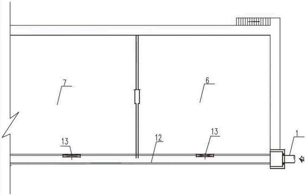
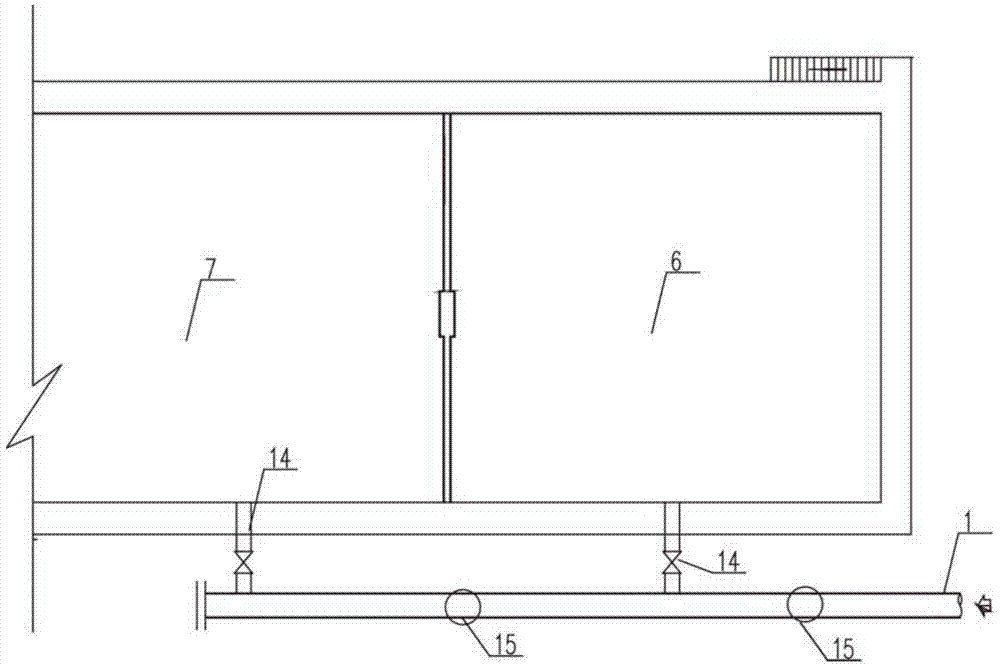
like figure 1 and figure 2 As shown, the first reaction pool 6, such as anaerobic pool, is used for biological phosphorus removal, and the second reaction pool 7, such as anoxic pool, is used for biological denitrification. Both anaerobic and anoxic sections require carbon sources. The traditional AAO process uses All enter the anaerobic tank through the water inlet pipe 1, so that the carbon source of the anoxic tank is insufficient. There are two types, one is that the sewage enters the anaerobic and anoxic sections respectively in the form of adjusting the weir plate 13 along the channel 12, and it is impossible to specifically measure the entry into the anaerobic and anoxic sections by adjusting the height of the weir plate 13 The flow rate brings inconvenience to the process adjustment; another water inlet method is to install valves on the water inlet pipes, and the sewage enters different pools through the water inlet branch pipes 14. To measure the flow rate, it is necessary to install a flow meter 15 on the pipes. To adjust the water intake, on the one hand, the cost of large-diameter pipes, regulating valves, and flowmeter 15 is increased. On the other hand, the flowmeter 15 has requirements for the installation length. Usually there is not enough space to install the flowmeter 15, resulting in inaccurate measurement. , so that the AAO process with multi-point water inflow cannot be effectively adjusted

Method used


Image

  • A biochemical pool water distribution system
  • A biochemical pool water distribution system
  • A biochemical pool water distribution system

Examples


Embodiment Construction

[0026] The specific implementation manners of the present invention will be further described in detail below in conjunction with the accompanying drawings and embodiments. The following examples are used to illustrate the present invention, but are not intended to limit the scope of the present invention.

[0027] In the description of the present invention, it should be noted that the terms "center", "longitudinal", "transverse", "upper", "lower", "front", "rear", "left", "right", " The orientations or positional relationships indicated by "vertical", "horizontal", "top", "bottom", "inner", "outer", etc. are based on the orientation or positional relationships shown in the drawings, and are only for the convenience of describing the present invention and simplifying Describes, but does not indicate or imply that the device or element referred to must have a specific orientation, be constructed in a specific orientation, and operate in a specific orientation, and therefore sh...


PUM

PropertyMeasurementUnit
lengthaaaaaaaaaa

Abstract

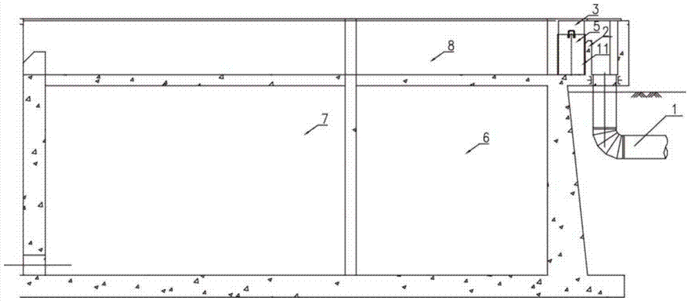
The invention relates to the field of sewage treatment, and discloses a water inlet distribution system for a biochemical pool, comprising a water inlet pipe, a first reaction pool, a second reaction pool, an inlet buffer tank, an overflow weir, an inlet distribution tank and an inlet channel. The water pipe leads into the water inlet buffer tank, the overflow weir is arranged at the outlet of the water inlet buffer tank, the water inlet distribution tank is arranged between the overflow weir and the outer wall of the first reaction tank, and the water inlet distribution The groove includes two side walls arranged in parallel, and a plurality of sets of vertical slide slots opposite to each other are arranged between the two side walls, wherein a set of vertical slide slots is provided with a sliding partition, and the sliding partition divides the The water inlet distribution tank is divided into first and second water inlet areas, the first reaction pool is connected with the first water inlet area, the water inlet channel is set along the same side of the first reaction pool and the second reaction pool, and the The water inlet channel communicates with the second water inlet area and the second reaction pool. The invention has convenient adjustment and accurate measurement, and can realize the effective deployment of influent carbon sources in anoxic and anaerobic sections.

Description

technical field [0001] The invention relates to the technical field of sewage treatment, in particular to an AAO biochemical pool water inlet distribution system. Background technique [0002] At present, the anaerobic-anoxic-aerobic (AAO) process is a stable biochemical treatment process for enhanced nitrogen and phosphorus removal. Through reasonable adjustment, the effluent can reach the first level of the national "Urban Wastewater Treatment Plant Pollutant Discharge Standard" A standard. [0003] The biochemical reaction tank of the traditional anaerobic-anoxic-aerobic process consists of three sections: anaerobic, anoxic and aerobic. Such as figure 1 with figure 2 As shown, the first reaction pool 6, such as anaerobic pool, is used for biological phosphorus removal, and the second reaction pool 7, such as anoxic pool, is used for biological denitrification. Both anaerobic and anoxic sections require carbon sources. The traditional AAO process uses All enter the an...

Claims


Application Information

Patent Timeline
Patent Type & Authority Patents(China)
IPC IPC(8): C02F3/30
Inventor 周丽颖李星文杨大蔚仲崇川袁琳
Owner THUNIP CORP LTD
Why Eureka
Try Eureka