
A thread trimmer drive mechanism for a sewing machine

A driving mechanism and a technology for a sewing machine, which are applied to a thread cutting mechanism in a sewing machine, a sewing machine element, a control device for a sewing machine, etc., can solve the problems of occupying the interior installation space of a sewing machine table, complicated structure of the sewing machine table, and increased production costs, etc. Achieve the effect of saving installation space, saving thread trimming time and prolonging service life

Active Publication Date: 2017-08-25
ZHEJIANG ZOJE SEWING MACHINE
View PDF6 Cites 0 Cited by
  • Summary
  • Abstract
  • Description
  • Claims
  • Application Information

AI Technical Summary

Problems solved by technology

[0003] However, the existing bobbin thread trimming mechanism and upper thread trimming mechanism are all independently driven by corresponding driving parts, that is, the bobbin thread cutting mechanism and the upper thread trimming mechanism are respectively equipped with a corresponding driving part to carry out the driving work. The two are independent of each other and driven separately, resulting in low overall thread trimming efficiency, insufficient synchronization, and easy extension of thread trimming time
In addition, since the bottom thread trimming mechanism and the upper thread trimming mechanism are both arranged in the table of the sewing machine, the internal installation space of the sewing machine table itself is relatively narrow, and two driving parts are used to respectively control the bottom thread cutting mechanism and the upper thread cutting mechanism. The drive will also increase the production cost, occupy the internal installation space of the sewing machine table, and also cause the structure inside the sewing machine table to become more complicated, making the maintenance of various mechanisms more difficult

Method used


Image

  • A thread trimmer drive mechanism for a sewing machine
  • A thread trimmer drive mechanism for a sewing machine
  • A thread trimmer drive mechanism for a sewing machine

Examples


Embodiment 1

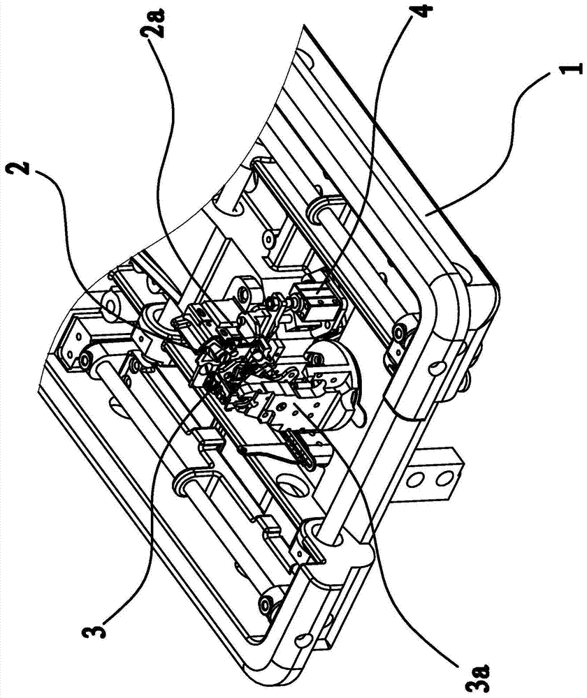
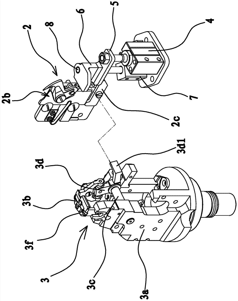
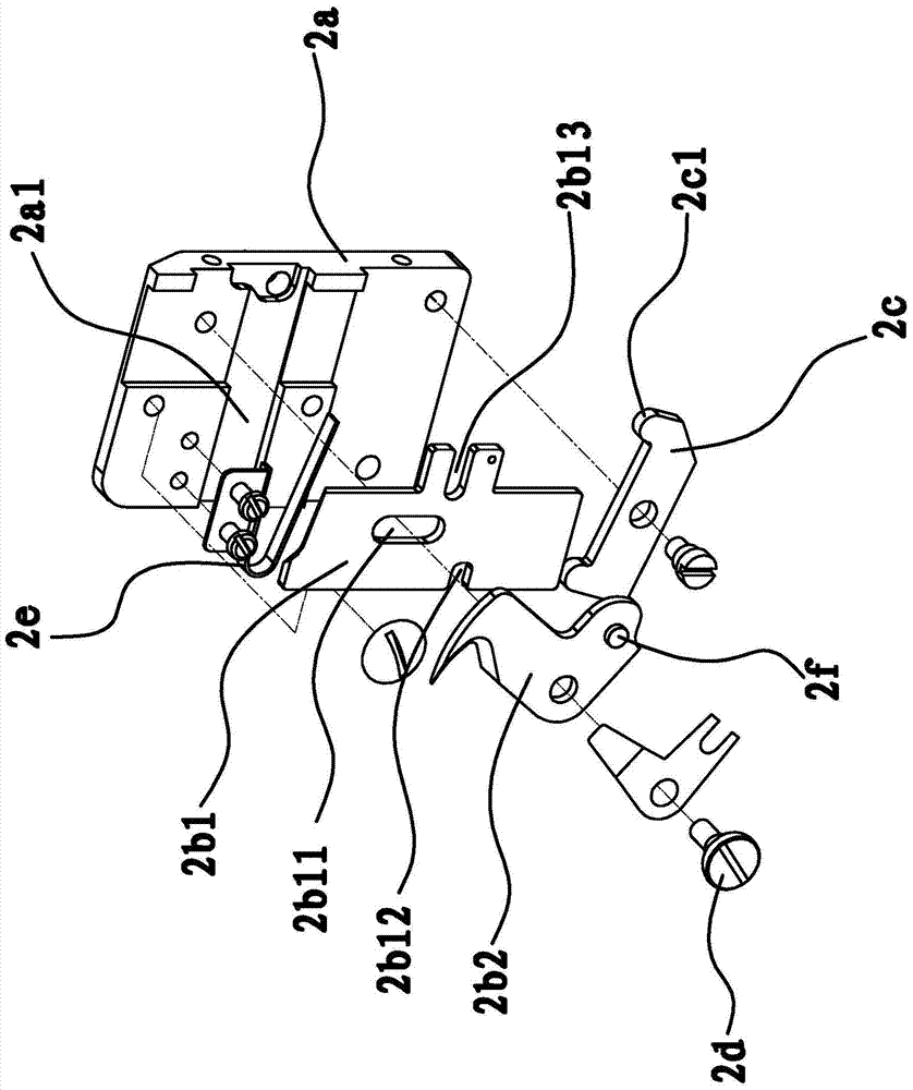
[0038] Such as figure 1 and figure 2 As shown, a thread trimming driving mechanism of a sewing machine includes an upper thread trimming mechanism 3 , a bottom thread trimming mechanism 2 and a driving cylinder 4 arranged in a sewing machine table 1 . The bobbin thread cutting mechanism 2 includes a base 2a fixed in the sewing machine table 1. Bottom thread scissors 2b are vertically arranged on the base 2a. A transmission rod 2c is arranged below the bottom thread scissors 2b. The middle part of the transmission rod 2c is hinged on the base 2a. , the inner end of the transmission rod 2c abuts against the bottom of the bobbin thread scissors 2b. The end of the driving cylinder 4 is horizontally connected with a pressing plate 5, the outer end of the pressing plate 5 is connected with the piston rod of the driving cylinder 4, and the inner end of the pressing plate 5 abuts against the outer end of the transmission rod 2c. In this embodiment, there are protrusions 2c1 on both...


PUM


Abstract

The invention provides a thread trimming drive mechanism for sewing machines, and belongs to the technical field of machinery. The problem that the existing sewing machine is complex in structure as the lower thread trimming mechanism and the upper thread trimming mechanism are driven separately is solved. The thread trimming drive mechanism comprises an upper thread trimming mechanism and a lower thread trimming mechanism, both of which are arranged inside a sewing machine table. The lower thread trimming mechanism comprises a base fixed inside the sewing machine table. A pair of lower thread scissors is vertically arranged on the base. The upper thread trimming mechanism comprises a positioning seat fixed inside the sewing machine table. A pair of upper thread scissors is horizontally arranged on the positioning seat. The thread trimming drive mechanism further comprises a drive cylinder arranged inside the sewing machine table. Under the drive of the drive cylinder, the lower thread scissors can trim off a lower thread upward and the upper thread scissors can swing transversely to trim off an upper thread at the same time. The thread trimming drive mechanism is advantageous in that the lower thread trimming mechanism and the upper thread trimming mechanism can be driven by the same cylinder to work simultaneously, the installation space is saved, the internal structure is simplified, and the like.

Description

technical field [0001] The invention belongs to the technical field of machinery and relates to a sewing machine, in particular to a thread trimming driving mechanism of the sewing machine. Background technique [0002] With the continuous development of science and technology, the degree of automation of sewing machines is getting higher and higher. The existing sewing machines are generally equipped with automatic thread trimmers. The suture is cut to separate the suture from the fabric, which can save sewing time and reduce the labor intensity of sewing workers. Existing automatic thread trimmers generally include an upper thread trimmer and a lower thread trimmer. The upper thread trimmer is specially used to cut off the upper thread, and the lower thread trimmer is specially used to cut off the lower thread (and core thread). The structures of the bottom thread cutting mechanism and the upper thread cutting mechanism in the existing sewing machines are basically the sa...

Claims


Application Information

Patent Timeline
Patent Type & Authority Patents(China)
IPC IPC(8): D05B65/02D05B69/08
Inventor 李宗润葛荣刘占利卢孔贵楼俏军蒋陈静
Owner ZHEJIANG ZOJE SEWING MACHINE
Learn More