
Anchor rod torque amplifier

A technology of torque amplifiers and bolts, applied in the directions of transmission parts, gear transmissions, belts/chains/gears, etc., can solve the problems such as the inapplicability of mechanical multipliers without torque value adjustment of hydraulic wrenches, and achieve increased adaptability Effect

Inactive Publication Date: 2015-12-09
长治市科力机械有限公司
View PDF9 Cites 1 Cited by
  • Summary
  • Abstract
  • Description
  • Claims
  • Application Information

AI Technical Summary

Problems solved by technology

[0003] The present invention proposes a bolt torque amplifier, which solves the problems in the prior art that the mechanical multiplier has no torque value adjustment function and the inapplicability of the hydraulic wrench

Method used


Image

  • Anchor rod torque amplifier
  • Anchor rod torque amplifier

Examples


Embodiment 1

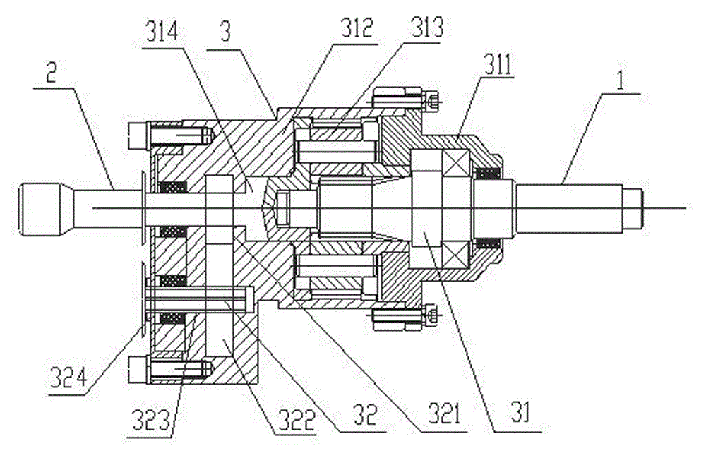
[0020] Example 1, such as figure 1 A bolt torque amplifier shown includes an input shaft 1, an output shaft 2, and a speed change transmission 3 arranged between the input shaft and the output shaft. The speed change transmission mechanism consists of a planetary gear reduction mechanism 31 and a primary gear reduction mechanism 32 Composition, the planetary gear reduction mechanism 31 includes a cover body 311, a ring gear sleeve 312 meshing with each other, three planetary gears 313 and a sun gear 315, one end of the ring gear sleeve 312 has an opening, and the cover body 311 is arranged at the opening and is connected with the The ring gear sleeve 312 is threaded to form a closed cavity in the ring gear sleeve, the sun gear is connected to the input shaft 1, and the three planetary gears 313 are connected to the planetary carrier 314, and the planetary carrier 314 is arranged in the closed cavity, and from It extends out and is threadedly connected with the output shaft 2; ...

Embodiment 2

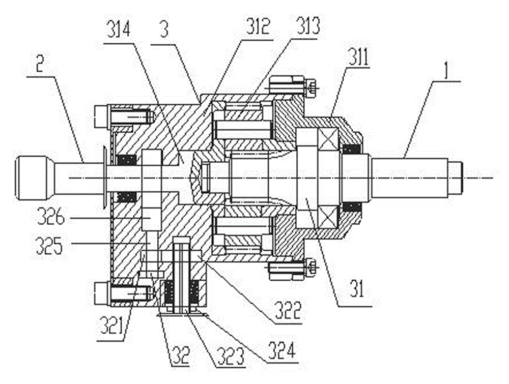
[0023] Example 2, such as figure 2 A bolt torque amplifier shown includes an input shaft 1, an output shaft 2, and a speed change transmission 3 arranged between the input shaft and the output shaft. The speed change transmission mechanism 3 consists of a planetary gear reduction mechanism 31 and a primary gear reduction mechanism 32. Composition, the planetary gear reduction mechanism 31 includes a cover body 311, a ring gear sleeve 312 meshing with each other, three planetary gears 313 and a sun gear 315, one end of the ring gear sleeve 312 has an opening, and the cover body 311 is arranged at the opening and is connected with the The ring gear sleeve 312 is threaded to form a closed cavity in the ring gear sleeve, the sun gear is connected to the input shaft 1, and the three planetary gears 313 are connected to the planetary carrier 314, and the planetary carrier 314 is arranged in the closed cavity, and from It extends out and is threadedly connected with the output shaft...


PUM


Abstract

The invention provides an anchor rod torque amplifier. The anchor rod torque amplifier comprises an input shaft, an output shaft and a speed changing transmission mechanism arranged between the input shaft and the output shaft. The speed changing transmission mechanism is composed of a planet gear speed reduction mechanism and a one-level gear speed reduction mechanism. The planet gear speed reduction mechanism comprises a tooth ring sleeve, three planet gears and a sun wheel which are engaged with one another. The sun wheel is connected with the input shaft. The planet gears are connected with a planet carrier. The one-level gear speed reduction mechanism comprises a drive wheel, a driven wheel and a wheel shaft carrying the driven wheel, the drive wheel is arranged at the output end of the planet carrier, and the wheel shaft is connected with the tooth ring sleeve through a spline bearing and extends out of the tooth ring sleeve. The wheel shaft is slid so that when the drive wheel and the driven wheel are engaged, the output end of the wheel shaft and the output shaft can be in threaded connection. The wheel shaft is slid so that when the drive wheel and the driven wheel are separated, the output end of the planet carrier and the output shaft can be connected. According to the anchor rod torque amplifier, the output torque can be adjusted, and adaptability is high.

Description

technical field [0001] The invention relates to the field of torque amplification, in particular to a bolt torque amplifier. Background technique [0002] Bolt-net support is a mature technology widely popularized and applied in coal mine roadway support at present. The key to the quality of bolt-net support is whether the bolt pre-tightening force meets the design requirements, so the role of bolt pre-tightening tools is particularly important. From the perspective of the current domestic coal mining industry, the development of bolt pretensioning tools is relatively lagging behind. Although there are a wide variety of multipliers or hydraulic wrenches and other related products, they all have limitations. The mechanical multiplier currently used has no torque value adjustment function; although the hydraulic wrench used has the torque value adjustment function, the safety regulations of the coal mine do not allow the power to be drawn from the roadheader on the tunneling f...

Claims


Application Information

Patent Timeline
Patent Type & Authority Applications(China)
IPC IPC(8): F16H1/32F16H57/023
CPCF16H1/32F16H57/023F16H2001/327
Inventor 刘秋来曹治国王国平
Owner 长治市科力机械有限公司
Learn More