Cloud measurement and control boiler system automatically discharging sewage according to sewage discharging ratio

A boiler and blowdown valve technology, applied in the field of boilers, can solve the problem of inability to flexibly adjust control procedures and parameters, and achieve the effect of saving heat exchange, preventing waste of heat energy, and optimizing structure

Inactive Publication Date: 2015-12-09
SHANDONG UNIV OF TECH
6 Cites 36 Cited by

AI-Extracted Technical Summary

Problems solved by technology

However, the on-site conditions of the system are complex and changeable. When the operation plan obtained by the local server cannot meet the needs of the on-site situation, maintenance personnel need to arrive at the site ...

Method used

As preferably, from the base angle of isosceles triangle to top angle, the range that the second cooling fin 18 width that extends from two waists of isosceles triangle increases more and more, from the top angle of isosceles triangle to the first At the end of the cooling fins 17, the width of the second cooling fins 19 extending from the first cooling fins 17 decreases gradually. It is found through experiments that the above setting can increase the heat dissipation effect by about 16% compared with the same increase or decrease. Therefore, it has a good heat dissipation effect.
As preferably, the device of measuring steam temperature and pressure is set in steam drum, and described device is connected with monitoring and diagnosis controller 20 data, and monitoring and diagnosis controller 20 calculates steam according to the temperature and pressure of measurement and water level height in steam drum The quality of the steam in the bag. In this way, in the previous calculation, the opening of the blowdown valve is controlled according to the ratio of the quality change of steam in the steam drum, the quality of output steam and the change of water in the steam drum to the quality of water input to the boiler. Spend. This makes the calculation results more accurate.
As preferably, the temperature of water in the measurement steam drum and the device of steam drum pressure are set, and described device is connected with monitoring and diagnosis controller 20 data, and monitoring diagnosis controller 20 calculates the temperature of water in the steam drum according to the temperature and the pressure of measurement quality changes. Calculating the mass of water through temperature and pressure makes the result more accurate.
Generally heat pipes are all around or both sides are provided with fins, but found in engineering, the convective heat transfer effect of the heat sink on the side contacting with the wall is generally not good, because the relatively poor flow of air on the wall side , so the present invention sets the base 22 of the isosceles triangle as a plane, so when installing the heat sink, the plane can be directly in close contact with the wall. Compared with other heat sinks, the installation space can be greatly saved, and space waste can be avoided. At the same time, a special form of heat sink is adopted to ensure the best heat dissipation effect.
[0060] Preferably, the waste heat utilization heat exchanger 2 is connected to the sewage pipeline, so that the heat of the sewage can be fully utilized. The cold source inlet pipe of the heat exchanger 2 is provided with a valve 9, the valve 9 is connected to the valve adjustment device 10, and the valve adjustment device 10 is connected to the monitoring and diagnosis controller 20 for data connection, so as to transmit the opening data of the valve 9 to the monitoring and diagnosis The controller 20 accepts instructions from the monitoring and diagnosing controller 20 at the same time. If the blowdown measured by the monitoring and diagnosing controller 20 increases, the monitoring and diagnosing controller 20 increases the opening of the valve 9 through the valve adjusting device 10 to increase the amount of cold source entering the heat exchanger 2 and keep the cold output from the heat exchanger 2. The temperature of the source is kept constant while avoiding overheating of the cooling source. If the blowdown measured by the monitoring and diagnosing controller 20 decreases, the monitoring and diagnosing controller 20 reduces the opening of the valve 9 through the valve adjusting device 10 to reduce the amount of cold source entering the heat exchanger 2 and keep the output of the heat exchanger 2 The temperature of the cold source is constant, while avoiding the poor heating effect of the cold source. As a preference, multiple heat exchangers 2 can be provided.
[0066] As a preferred strategy, a water level gauge (not shown) is set in the steam drum 1, and the w...

Abstract

The invention provides a boiler system. The boiler system carries out automatic control according to the mass of discharged sewage and the amount of water input into a boiler. A monitoring diagnosis controller is in data connection with a cloud server, so that monitored data are transmitted to the cloud server, the cloud server is connected with a client side, and the client side can obtain the monitored data by means of the cloud server. By means of the client side, the sewage discharge operation condition can be mastered in time, sewage discharge parameters can be adjusted in time, and the situation that due to sewage discharge faults of the boiler, a large amount of heat wastes is avoided.

Application Domain

Boiler cleaning apparatusBoiler control +2

Technology Topic

Image

  • Cloud measurement and control boiler system automatically discharging sewage according to sewage discharging ratio
  • Cloud measurement and control boiler system automatically discharging sewage according to sewage discharging ratio
  • Cloud measurement and control boiler system automatically discharging sewage according to sewage discharging ratio

Examples

  • Experimental program(1)

Example Embodiment

[0034] The specific embodiments of the present invention will be described in detail below in conjunction with the accompanying drawings.
[0035] In this article, if there is no special explanation, when it comes to formulas, "/" means division, and "×" and "*" mean multiplication.
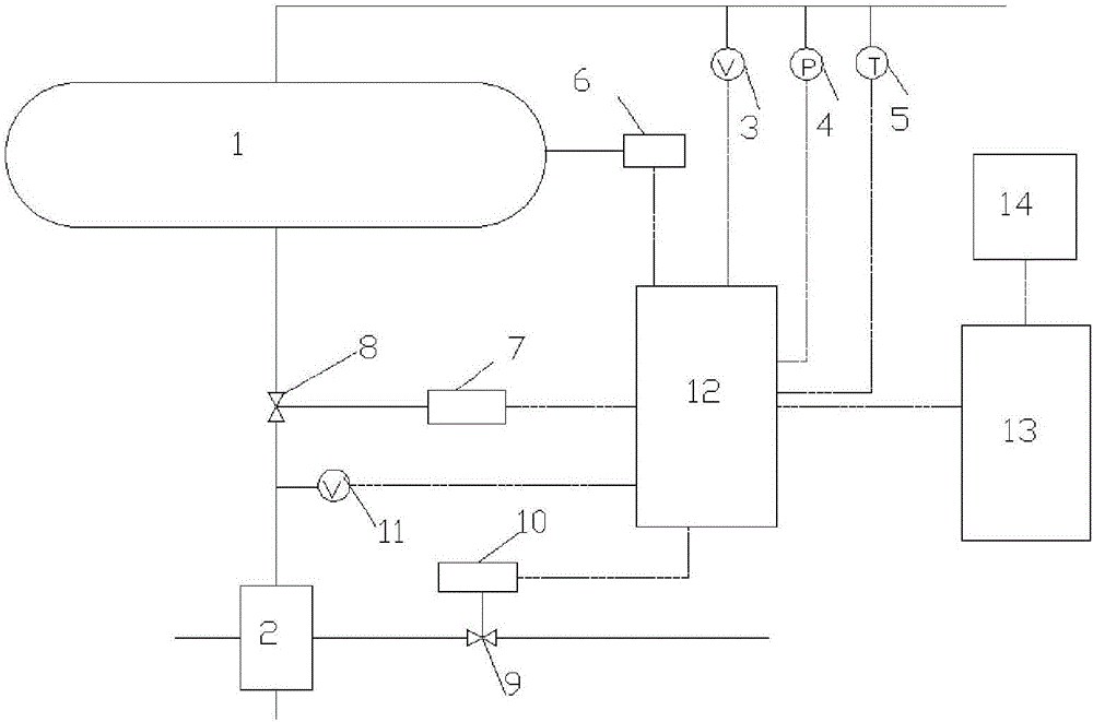
[0036] A boiler thermodynamic system, the boiler thermodynamic system includes at least one boiler for generating steam, and the boiler is in data connection with a monitoring and diagnosis controller 12 so as to monitor the operation of the boiler. The monitoring and diagnosis controller 12 is data-connected with the cloud server 13 so as to transmit the monitored data to the cloud server. The cloud server 13 is connected with the client 14, and the client 14 can obtain various monitoring information through the cloud server.
[0037] Advantageously, the client can input data to control the operation of the boiler system.
[0038] like figure 1 As shown, the boiler includes an automatic control blowdown system, and the automatic control blowdown system is automatically controlled according to the amount of steam generated by the boiler and the amount of water input into the boiler. If the ratio between the amount of steam and the amount of water input to the boiler is less than the lower limit value, the monitoring and diagnosis controller 12 automatically controls to reduce the blowdown amount. If the ratio between the amount of steam and the amount of water input to the boiler is greater than the upper limit value, the monitoring and diagnosis controller 12 automatically controls to increase the blowdown amount. The specific control system is as follows:
[0039] like figure 1 As shown, the boiler includes a flowmeter 3, a pressure gauge 4 and a thermometer 5 arranged on the steam outlet pipeline for measuring the flow rate, pressure and temperature of the output steam. The flowmeter 3, the pressure gauge 4 and the thermometer 5 are respectively connected to the monitoring and diagnostic controller 12 for data, so that the measured data is transmitted to the monitoring and diagnosing controller 12. In the monitoring and diagnosing controller, according to the measured steam temperature, pressure, The flow rate calculates the steam mass per unit of time.
[0040] The boiler includes a blowdown pipe arranged at the lower end of the boiler drum 1, a blowdown valve 8 is arranged on the blowdown pipe, and one end of the blowdown valve 8 is connected to a valve adjustment device 7, and the valve adjustment device 7 is connected to the monitoring and diagnostic controller 20 for data connection, so that the valve The opening data is transmitted to the monitoring and diagnosing controller 20 , and an instruction is received from the monitoring and diagnosing controller 20 to adjust the opening of the blowdown valve 8 .
[0041] The blowdown pipe further includes a flow meter 11 for measuring the blowdown flow. The flow meter 11 is in data connection with the monitoring and diagnosing controller 20 so as to transmit the data to the monitoring and diagnosing controller 20 . The monitoring and diagnosing controller 20 calculates the sewage discharge amount per unit time according to the flow rate, thereby calculating the sewage discharge quality. The sewage quality can be calculated by using the density of the empirical sewage, or by calling the data stored in the controller 20 by measuring the temperature and water quality of the sewage.
[0042] The total inlet pipe of the boiler is provided with a flow meter for detecting the flow entering the boiler, and the flow meter is connected with the monitoring and diagnosis controller 20 for data, so that the measured data is transmitted to the monitoring and diagnosis controller 20, and the monitoring and diagnosis The controller 20 calculates the flow of water entering the boiler per unit time according to the measured flow, so as to calculate the quality of the water. The quality of water can be calculated by using the density of water, or can be calculated by calling the data stored in the controller 20 by measuring the temperature of the water.
[0043]Of course, the water entering the boiler is the sum of the water volume of the circulating water pipe and the water supply pipe. As a preference, a flowmeter connected to the monitoring and diagnosis controller 20 can be respectively provided on the water supply pipe and the circulating water pipe, and the total amount of water entering the boiler per unit time can be calculated by calculating the sum of the two flows. The present invention can adopt various control strategies to control the amount of pollutant discharge.
[0044] A preferred control strategy is: if the ratio of the steam quality calculated by the monitoring and diagnostic controller 20 to the quality of water input to the boiler is less than the lower limit value, it indicates that the blowdown rate is too high, so the monitoring and diagnostic controller 20 automatically adjusts the value of the steam through the valve adjustment device 7. The opening of blowdown valve 8. Through the above operations, excessive sewage discharge can be avoided, resulting in waste of energy. If the ratio of the steam quality to the quality of water input to the boiler is greater than the upper limit, it indicates that the blowdown rate is too low, which may affect the life of the boiler, and the monitoring and diagnosis controller 20 automatically increases the opening of the blowdown valve 8 through the valve adjustment device 7 .
[0045] The monitoring and diagnosis controller 20 transmits the quality of steam, the quality of input boiler water and its ratio, and the opening of the blowdown valve 39 to the cloud server 13 , and the cloud server 13 transmits the above data to the client 14 .
[0046] The client 14 can input the value of the opening of the blowdown valve 8 according to the obtained data, and transmit it to the monitoring and diagnosis controller 20 through the cloud server 13, and manually adjust the opening of the blowdown valve through the monitoring and diagnosis controller.
[0047] Preferably, if the ratio of the steam quality to the water quality input to the boiler is still greater than the upper limit when the opening of the blowdown valve 8 is at its maximum, the client will issue a warning to indicate whether there is a failure in the blowdown system.
[0048] Preferably, if the ratio of the steam quality to the water quality input to the boiler is still less than the lower limit when the blowdown valve 8 is closed, the client will issue a warning to indicate whether the blowdown system is faulty.
[0049] A preferred control strategy is that when the ratio of the quality of the blown water detected by the monitoring and diagnosis controller 20 through the flowmeter 11 to the quality of the water input to the boiler exceeds the upper limit, it indicates that the amount of blowdown is too large, so the monitoring and diagnosis controller 20 regulates through the valve The device 7 automatically adjusts the opening of the blowdown valve 8 small. If the ratio of the quality of the detected sewage water to the water input to the boiler exceeds the lower limit, it indicates that the sewage discharge is too small, so the monitoring and diagnosis controller 20 automatically adjusts the opening of the sewage valve 8 through the valve adjustment device 7 . Through this setting, the water quality in the steam drum is avoided to be too poor, so as not to cause corrosion of the boiler steam drum.
[0050] The monitoring and diagnosis controller 20 transmits the quality of the discharged water, the quality of the water input to the boiler and its ratio, and the opening of the blowdown valve 8 to the cloud server 13, and the cloud server 13 transmits the above data to the client 14.
[0051] The client 14 can input the value of the opening of the blowdown valve 8 according to the obtained data, and transmit it to the monitoring and diagnosing controller 20 through the cloud server 13 , and manually adjust the opening of the blowdown valve through the monitoring and diagnosing controller 20 .
[0052] If the ratio of the quality of the blowdown water to the water input to the boiler is still less than the lower limit when the blowdown valve is opened to the maximum, the client will issue a warning;
[0053] If the ratio of the quality of blowdown water to the quality of water input to the boiler is still greater than the upper limit when the blowdown valve is closed, the client will issue a warning.
[0054] A preferred strategy, the steam drum 1 also includes a water quality analyzer 6 to measure the water quality in the steam drum. The water quality analyzer 6 is in data connection with the monitoring and diagnosis controller 20, so as to receive the measured data, and control the opening of the blowdown valve 8 according to the measured data. If the measured data shows that the water quality is too poor, for example, a certain index exceeds the upper limit of the data, timely sewage discharge is required, so the monitoring and diagnosis controller 20 automatically adjusts the opening of the sewage valve 8 through the valve adjustment device 7 . If the measured data shows that the water quality is good, the monitoring and diagnosis controller 20 automatically adjusts the opening of the blowdown valve 8 smaller through the valve adjusting device 7 . The blowdown valve can even be closed if necessary.
[0055] The monitoring and diagnosis controller 20 transmits the water quality data measured in the steam drum and the opening degree of the blowdown valve 8 to the cloud server 13 , and the cloud server 13 transmits the above data to the client 14 .
[0056] The client 14 can input the value of the opening of the blowdown valve 8 according to the obtained data, and transmit it to the monitoring and diagnosing controller 20 through the cloud server 13 , and manually adjust the opening of the blowdown valve through the monitoring and diagnosing controller 20 .
[0057] A preferred strategy is to install a water quality analyzer (not shown) on the sewage pipe to measure the water quality in the sewage pipe. The water quality analyzer is in data connection with the monitoring and diagnosis controller 20, so as to receive the measured data, and control the opening of the blowdown valve according to the measured data. If the measured data shows that the water quality is too poor, for example, a certain index exceeds the upper limit of the data, timely sewage discharge is required, so the monitoring and diagnosis controller 20 automatically adjusts the opening of the sewage valve 8 through the valve adjustment device 7 . If the measured data shows that the water quality is good, the monitoring and diagnosis controller 20 automatically adjusts the opening of the blowdown valve 8 smaller through the valve adjusting device 7 . The blowdown valve can even be closed if necessary.
[0058] The monitoring and diagnosis controller 20 transmits the measured water quality data in the sewage pipe and the opening of the sewage valve 8 to the cloud server 13 , and the cloud server 13 transmits the above data to the client 14 .
[0059] The client 14 can input the value of the opening of the blowdown valve 8 according to the obtained data, and transmit it to the monitoring and diagnosing controller 20 through the cloud server 13 , and manually adjust the opening of the blowdown valve through the monitoring and diagnosing controller 20 .
[0060] As a preference, the waste heat utilization heat exchanger 2 is connected to the sewage discharge pipe so as to make full use of the heat of the sewage. The cold source inlet pipe of the heat exchanger 2 is provided with a valve 9, the valve 9 is connected to the valve adjustment device 10, and the valve adjustment device 10 is connected to the monitoring and diagnosis controller 20 for data connection, so as to transmit the opening data of the valve 9 to the monitoring and diagnosis The controller 20 accepts instructions from the monitoring and diagnosing controller 20 at the same time. If the blowdown measured by the monitoring and diagnosing controller 20 increases, the monitoring and diagnosing controller 20 increases the opening of the valve 9 through the valve adjusting device 10 to increase the amount of cold source entering the heat exchanger 2 and keep the cold output from the heat exchanger 2. The temperature of the source is kept constant while avoiding overheating of the cooling source. If the blowdown measured by the monitoring and diagnosing controller 20 decreases, the monitoring and diagnosing controller 20 reduces the opening of the valve 9 through the valve adjusting device 10 to reduce the amount of cold source entering the heat exchanger 2 and keep the output of the heat exchanger 2 The temperature of the cold source is constant, while avoiding the poor heating effect of the cold source. As a preference, multiple heat exchangers 2 can be provided.
[0061] The monitoring and diagnosis controller 20 transmits the measured opening degree of the valve 9 and the opening degree of the blowdown valve 8 to the cloud server 13 , and the cloud server 13 transmits the above data to the client 14 .
[0062] The client 14 can input the value of the opening of the valve 9 according to the obtained data, and transmit it to the monitoring and diagnosing controller 20 through the cloud server 13, and manually adjust the opening of the blowdown valve through the monitoring and diagnosing controller 20.
[0063] As a preferred strategy, the monitoring and diagnosing controller 20 can calculate the water loss of the boiler by calculating the ratio of the sum of steam quality and blowdown quality to the quality of water input to the boiler. If the calculated water loss exceeds the upper limit, the monitoring and diagnosing controller 20 will send out an alarm prompt.
[0064] The monitoring and diagnosis controller 20 transmits the ratio data of steam quality, sewage quality, water quality input to the boiler and the sum of steam quality and sewage quality to the quality of water input to the boiler to the cloud server 13, and the cloud server 13 transmits the above data to the client 14.
[0065] If the calculated water loss exceeds the upper limit, the client 13 sends an alarm prompt.
[0066] As a preferred strategy, a water level gauge (not shown) is set in the steam drum 1 , and the water level gauge is in data connection with the monitoring and diagnosing controller 20 so as to transmit measurement data to the monitoring and diagnosing controller 20 . The monitoring and diagnosing controller 20 calculates the change of the water level per unit time according to the measured data, so as to calculate the quality change of the water in the steam drum 1 per unit time. The monitoring and diagnosing controller 20 adjusts the opening of the blowdown valve 8 according to changes in the amount of steam produced, the amount of water input by the boiler, and the amount of water in the steam drum. If the ratio of the sum of the steam quality calculated by the monitoring and diagnosing controller 20 plus the quality change of boiler steam drum 1 water to the quality of water input to the boiler is lower than a certain value, it indicates that the blowdown rate is too high, so the monitoring and diagnosing controller 20 passes The valve adjusting device 7 automatically adjusts the opening of the blowdown valve 8 small. Through the above operations, excessive sewage discharge can be avoided, resulting in waste of energy. By adding the drum water level detection, the accuracy of the measured data is further increased.
[0067] The monitoring and diagnosis controller 20 will measure the water level, the quality change of the water in the steam drum 1 per unit time, the amount of steam produced, the water volume input by the boiler, and the sum of the steam quality plus the quality change of the boiler steam drum 1 water and the water input into the boiler. The ratio data of the quality is transmitted to the cloud server 13, and the cloud server 13 transmits the above data to the client 14.
[0068] The client 14 can input the value of the opening of the valve 9 according to the obtained data, and transmit it to the monitoring and diagnosing controller 20 through the cloud server 13, and manually adjust the opening of the blowdown valve through the monitoring and diagnosing controller 20.
[0069] As a preferred strategy, the monitoring and diagnosing controller 20 can calculate the water loss of the boiler by calculating the ratio of the sum of steam quality, drum water change quality and blowdown quality to the quality of water input to the boiler. If the calculated water loss exceeds the upper limit, the monitoring and diagnosing controller 20 will send out an alarm prompt.
[0070] The monitoring and diagnosis controller 20 transmits the steam quality, the changing quality of the drum water and the blowdown quality, and the ratio data of the sum of the steam quality, the change quality of the drum water and the blowdown quality to the quality of water input into the boiler to the cloud server 13. The cloud server 13 transmits the above data to the client 14.
[0071] If the calculated water loss exceeds the upper limit, the client 13 sends an alarm prompt.
[0072] Preferably, a device for measuring the temperature of water in the steam drum and the pressure of the steam drum is provided, the device is connected to the monitoring and diagnosis controller 20 for data, and the monitoring and diagnosis controller 20 calculates the quality change of the water in the steam drum according to the measured temperature and pressure. Calculating the mass of water through temperature and pressure makes the result more accurate.
[0073] The monitoring and diagnosis controller 20 transmits the temperature of the water in the steam drum and the data of the steam drum pressure to the cloud server 13 , and the cloud server 13 transmits the above data to the client 14 .
[0074] As preferably, a device for measuring steam temperature and pressure is arranged in the steam drum, and the device is connected with the monitoring and diagnosis controller 20 data, and the monitoring and diagnosis controller 20 calculates the steam temperature in the steam drum according to the measured temperature and pressure and the water level in the steam drum. the quality of. In this way, in the previous calculation, the opening of the blowdown valve is controlled according to the ratio of the quality change of steam in the steam drum, the quality of output steam and the change of water in the steam drum to the quality of water input to the boiler. Spend. This makes the calculation results more accurate.
[0075] Similarly, when calculating the loss of water, it is also necessary to compare the sum of the quality change of steam in the steam drum, the quality of output steam, the quality change of water in the steam drum, and the amount of blowdown with the input water volume of the boiler.
[0076] Preferably, a thermometer can be set on the blowdown pipe, and the monitoring and diagnosis controller 20 can calculate the quality of blowdown water per unit time according to the blowdown water temperature, water composition and flow rate.
[0077]Preferably, the relationship data between temperature, pressure and density of the steam is stored in the monitoring and diagnosis controller 20 in advance, so as to calculate the quality of the steam. It is also possible to store the temperature-density relationship data of water in advance, and calculate the mass of water in the steam drum at the same time. The relationship between the temperature, composition and density of the sewage is also pre-stored in the monitoring and diagnosis controller 20 .
[0078] All the measurement data and calculation data mentioned above can be sent to the cloud server 13 through the monitoring and diagnosis controller 20 , and the cloud server 13 transmits the above data to the client 14 . The client can get the information of system operation in time.
[0079] Preferably, the heat exchanger is a heating radiator. Of course, sewage can directly enter the heating radiator for heating, such as figure 1 shown. Of course, the circulating water in the radiator can also be circulated to the heating radiator for heating after exchanging heat with the sewage through the heat exchanger.
[0080] The radiator includes an upper header and a lower header, and a cooling pipe is connected between the upper header and the lower header, such as figure 2 , 3 As shown, the heat pipe includes a base pipe 15 and cooling fins 17-19 located on the periphery of the base pipe, as figure 2 , 3 As shown, the cross-section of the base pipe is an isosceles triangle, and the heat dissipation fins include a first heat dissipation fin 17 and a second heat dissipation fin 18, 19, and the first heat dissipation fin 17 is outward from the apex of the isosceles triangle Extended, the second cooling fins 18, 19 include a plurality of cooling fins 18 extending outward from the two sides of the isosceles triangle and a plurality of cooling fins 19 extending outward from the first cooling fins, toward the same The second cooling fins 18 and 19 extending in the same direction are parallel to each other. The second fins 18 and 19 extending outward from the first waist 20 of the triangle (that is, the waist on the right) are parallel to each other, and the extending ends of the first fin 17 and the second fins 18 and 19 form a second isosceles triangle ,like figure 2 As shown, the length of the waist of the second isosceles triangle is S; the first fluid passage 16 is arranged inside the base pipe 15, the second fluid passage 24 is arranged inside the first heat sink 17, and the first fluid passage 17 communicates with the second fluid channel 24 . For example, if figure 2 As mentioned above, they are connected at the vertices of the isosceles triangle.
[0081] Generally, heat sinks are installed around or on both sides of the heat pipe, but it is found in the project that the heat sink on the side that is in contact with the wall is generally not effective in convective heat transfer, because the air flow on the wall side is relatively poor, so this The invention sets the base 22 of the isosceles triangle as a plane, so when installing the heat sink, the plane can be directly in contact with the wall. Compared with other radiators, it can greatly save the installation space and avoid space waste. At the same time, a special The heat sink form ensures the best heat dissipation effect.
[0082] Preferably, the second cooling fins 18 and 19 are mirror-symmetrical to the plane where the midline of the first cooling fin 17 is located, that is, mirror-symmetrical to the plane where the line connecting the midpoint of the apex and the base of the isosceles triangle is located.
[0083] Preferably, the second cooling fins extend perpendicular to the two legs of the second isosceles triangle.
[0084] When the length of the sides of the isosceles triangle is constant, the longer the first heat sink 17 and the second heat sink 18, 19, the better the heat exchange effect in theory. It was found during the test that when the first heat sink and the second heat sink When the second heat sink reaches a certain length, the heat transfer effect does not increase significantly, mainly because as the length of the first heat sink and the second heat sink increases, the temperature at the end of the heat sink becomes lower and lower. If it is reduced to a certain extent, the heat transfer effect will not be obvious, on the contrary, the cost of materials will be increased and the space occupied by the radiator will be greatly increased. At the same time, during the heat transfer process, if the distance between the second heat sinks is too small , It is also easy to cause the deterioration of the heat exchange effect, because as the length of the heat pipe increases, the boundary layer becomes thicker during the air rise, causing the boundary layers between adjacent heat sinks to overlap each other, which deteriorates heat transfer, and the length of the heat pipe is too low or The distance between the second cooling fins is too large to reduce the heat exchange area and affect the heat transfer. An optimal dimensional relationship is satisfied between the length of the radiator and the length of the radiator base.
[0085] Therefore, the present invention summarizes the best size optimization relationship of the radiator through thousands of test data of radiators of different sizes.
[0086] The distance between the adjacent second cooling fins is L1, the length of the base of the isosceles triangle is W, and the length of the waist of the second isosceles triangle is S. The relationship between the above three satisfies the following formula:
[0087] L1/S*100=A*Ln(L1/W*100)+B*(L1/W)+C, where Ln is a logarithmic function, A, B, and C are coefficients, 0.68 < B<26, 7.5
[0088] 0.09 <0.11,0.11 <0.13
[0089] 4mm
[0090] 40mm
[0091] 45mm
[0092] The apex angle of an isosceles triangle is a, 110°
[0093] Preferably, the base pipe length is L, 0.02 <0.08, 800mm
[0094] As preferred, A=0.69, B=24.6, C=8.3.
[0095] It should be noted that the distance L1 between adjacent second heat sinks is the distance calculated from the center of the second heat sink, as figure 1 as shown.
[0096] After calculating the results, the test is carried out. By calculating the boundary and intermediate values, the results obtained are basically consistent with the formula. The error is basically within 3.54%, the largest relative error is not more than 3.97%, and the average error is 2.55%.
[0097] Preferably, the distances between the adjacent second cooling fins are the same.
[0098] Preferably, the width of the first heat sink is larger than the width of the second heat sink.
[0099] Preferably, the width of the first heat sink is b1, and the width of the second heat sink is b2, wherein 2.2*b2
[0100] Preferably, 0.9mm
[0101] Preferably, the width of the second fluid channel is 0.85-0.95 times, preferably 0.90-0.92 times, the width of the second heat sink.
[0102] The widths b1 and b2 here refer to the average width of the heat sink.
[0103] Preferably, holes 23 are provided on the first and/or second cooling fins for breaking the bottom layer of laminar flow. The main reason is that the second heat sink mainly exchanges heat through air convection, and the air flows upwards from the bottom of the second heat sink by natural convection. During the upward flow of air, the thickness of the boundary layer continues to increase, and even finally As a result, the boundary layers between adjacent second heat sinks overlap, which will lead to deterioration of heat exchange. Therefore, the boundary layer can be destroyed by setting the hole 9, thereby enhancing heat transfer.
[0104] Preferably, the hole 23 is semicircular or circular in shape.
[0105] Preferably, the hole 23 runs through the entire heat sink.
[0106] As a preference, along the direction of air flow, that is, from the bottom of the radiator to the top of the radiator, the area of ​​the holes 23 increases continuously. The main reason is that along the direction of air flow, the thickness of the boundary layer increases continuously. Therefore, by setting the area of ​​the hole 23 to increase continuously, the degree of damage to the boundary layer can be continuously increased, thereby enhancing heat transfer.
[0107] Preferably, the hole 23 with the largest area is 1.25-1.37 times, preferably 1.32 times, the smallest area.
[0108] As a preference, along the air flow direction, that is, from the bottom of the radiator to the top of the radiator, the density (that is, the number) of the holes 23 increases continuously. The main reason is that along the direction of air flow, the thickness of the boundary layer increases continuously. Therefore, by setting the density of holes 23 that increases continuously, the degree of damage to the boundary layer can be continuously increased, thereby enhancing heat transfer.
[0109] Preferably, the density of the densest part of the holes 23 is 1.26-1.34 times, preferably 1.28 times, that of the sparsest part.
[0110] As a preference, on the same second heat sink, the area of ​​each hole 239 is continuously reduced from the root of the heat sink (ie, the connection portion with the base pipe 15 ) to the top of the heat sink. The main reason is that the temperature of the heat sink continuously decreases from the root of the heat sink to the top of the heat sink, so the thickness of the boundary layer is continuously reduced. By setting the area of ​​the hole 23 that changes, the thickness of different positions that destroy the boundary layer can be realized, thereby Save material.
[0111] Preferably, the change of the area of ​​the holes 23 is directly proportional to the absolute temperature on the heat sink.
[0112] As a preference, on the same second heat sink, the density of the holes 23 decreases continuously from the root of the heat sink (ie, the connection portion with the base pipe 1 ) to the top of the heat sink. The main reason is that the temperature of the heat sink continuously decreases from the root of the heat sink to the top of the heat sink, so that the thickness of the boundary layer is continuously reduced. By setting the density of the changed holes 23, the thickness of different positions that destroy the boundary layer can be realized, thereby Save material.
[0113] Preferably, the change of the density of the holes 23 is directly proportional to the absolute temperature on the heat sink.
[0114] Preferably, the width b2 between the second cooling fins is changed according to a certain rule, and the specific rule is from the bottom corner of the isosceles triangle to the top corner, and the width of the second cooling fins 18 extending from the two waists of the isosceles triangle. The width becomes larger and larger, and the width of the second cooling fin 19 extending from the first cooling fin 18 becomes smaller and smaller from the vertex of the isosceles triangle to the end of the first cooling fin 17 . The main reason is that the heat dissipation of the second heat sink at the waist gradually increases from the bottom corner to the top corner, so the heat dissipation area needs to be increased, so the heat dissipation area of ​​the heat sink is increased by increasing the width of the heat sink. Similarly, along the first heat sink 18 , from the bottom to the end, the amount of heat dissipation becomes less and less, so the area of ​​the heat sink is correspondingly reduced. By setting in this way, the heat dissipation efficiency can be greatly improved, and at the same time, the material can be greatly saved.
[0115] As preferably, from the bottom corner of the isosceles triangle to the top corner, the width of the second cooling fin 18 extending from the two waists of the isosceles triangle increases more and more, and from the top corner of the isosceles triangle to the first cooling fin 17 The width of the second cooling fins 19 extending from the first cooling fins 17 decreases less and less. It is found through experiments that the above setting can increase the heat dissipation effect by about 16% compared with the same increase or decrease. Therefore, it has a good heat dissipation effect.
[0116] Although the present invention has been disclosed above with preferred embodiments, the present invention is not limited thereto. Any person skilled in the art can make various changes and modifications without departing from the spirit and scope of the present invention, so the protection scope of the present invention should be based on the scope defined in the claims.

PUM

no PUM

Description & Claims & Application Information

We can also present the details of the Description, Claims and Application information to help users get a comprehensive understanding of the technical details of the patent, such as background art, summary of invention, brief description of drawings, description of embodiments, and other original content. On the other hand, users can also determine the specific scope of protection of the technology through the list of claims; as well as understand the changes in the life cycle of the technology with the presentation of the patent timeline. Login to view more.

Similar technology patents

Energy-saving type instant-heating water dispenser

ActiveCN105125078AEfficient use of steam heatAvoid heat wasteBeverage vesselsThin walledEngineering
Owner:NINGBO CIXI ELECTRICAL APPLIANCE

Boiler system capable of intelligently controlling pollution discharge time based on cloud computing

InactiveCN107289439AAvoid heat wasteReduce lagBoiler cleaning control devicesSteam boilersAutomatic controlWater quality
Owner:ZHONGBEI UNIV

Constant-temperature automatic control system for circulating water pump based on stable frequency oscillation circuit

InactiveCN105201803BAvoid heat wasteExtend working lifePump controlPositive-displacement liquid enginesAutomatic Generation ControlVariable-frequency drive
Owner:宜宾摩米创新工场电子科技有限公司

Classification and recommendation of technical efficacy words

  • Avoid heat waste
  • Optimize structure

Boiler system capable of intelligently controlling pollution discharge time based on cloud computing

InactiveCN107289439AAvoid heat wasteReduce lagBoiler cleaning control devicesSteam boilersAutomatic controlWater quality
Owner:ZHONGBEI UNIV

Energy-saving type instant-heating water dispenser

ActiveCN105125078AEfficient use of steam heatAvoid heat wasteBeverage vesselsThin walledEngineering
Owner:NINGBO CIXI ELECTRICAL APPLIANCE

High oil absorption resin based on rubber and its preparation method

InactiveCN1869090AOptimize structureSmall steric hindranceSolventDispersed media
Owner:DONGHUA UNIV

Full-automatic vertical PE (Poly Ethylene) film packaging machine

ActiveCN104401522AOptimize structureReduce shaft diameterWrapping material feeding apparatusWeb rotation wrappingElectric machineryAutomatic control
Owner:中轻长泰(长沙)智能科技股份有限公司
Why Eureka
Try Eureka