Eureka AIR delivers breakthrough ideas for toughest innovation challenges, trusted by R&D personnel around the world.

Air conditioner system

An air-conditioning system and cabinet technology, applied in the direction of machine operation, heating and cooling combination, refrigerator, etc., can solve the problems of single function, heat waste, and temperature drop of air conditioners, so as to realize comprehensive utilization and ensure normal refrigeration , Solve the effect of heat waste

Pending Publication Date: 2017-08-18
GD MIDEA AIR-CONDITIONING EQUIP CO LTD +1
View PDF8 Cites 0 Cited by
  • Summary
  • Abstract
  • Description
  • Claims
  • Application Information

AI Technical Summary

Problems solved by technology

[0002] In the related art, the function of the air conditioner is relatively single, and generally only has the function of adjusting the indoor temperature.
When cooling, the evaporator absorbs heat to lower the temperature in the room, while the heat released by the condenser is discharged to the atmosphere in the form of hot air, resulting in a large amount of heat waste.
And while the air conditioner is cooling down, it will keep taking away the moisture in the room, making the indoor air very dry. If you turn on the air conditioner for a long time, you will feel dry throat and thirst. In addition, the condensed water produced by the air conditioner during operation It will be discharged to the outside through the drain pipe. Since the installer did not deal with the drain pipe, people passing by downstairs will often be drenched by the drained water, causing a lot of inconvenience to people's lives.
Most direct drinking machines use ultrafiltration membranes and activated carbon to filter and purify tap water, but their obvious disadvantage is that the filter elements need to be replaced frequently, which is not only troublesome but also expensive, and is not accepted by ordinary people.

Method used


Image

  • Air conditioner system
  • Air conditioner system
  • Air conditioner system

Examples


Embodiment 1

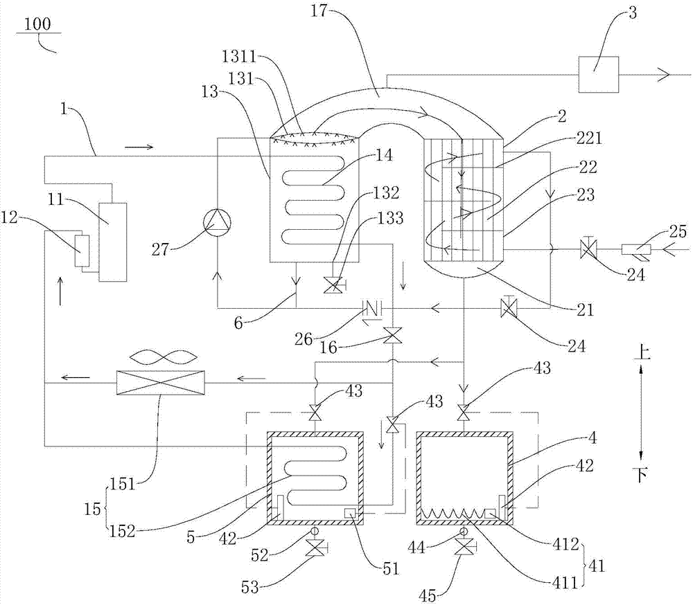
[0077] Such as figure 1 As shown, the air conditioning system 100 according to the embodiment of the present invention includes a refrigeration circuit 1 , a preheater 2 , a vacuum pump 3 , a first water tank 4 and a second water tank 5 .

[0078] Specifically, the refrigeration circuit 1 includes a condensation box 13 , a first condenser 14 , a first evaporator 151 and a second evaporator 152 . The first condenser 14 is arranged in the condensing box body 13, the first evaporator 151 and the second evaporator 152 are connected in parallel, the first condenser 14 is connected in series with the first evaporator 151 and the second evaporator 152 respectively, and in the compressor 11 The high-temperature and high-pressure refrigerant first flows into the first condenser 14 for heat exchange, then flows through the electronic expansion valve 16 connected in series to the refrigeration circuit 1 to throttle and reduce pressure, and then flows to the first evaporator 151 and the s...

Embodiment 2

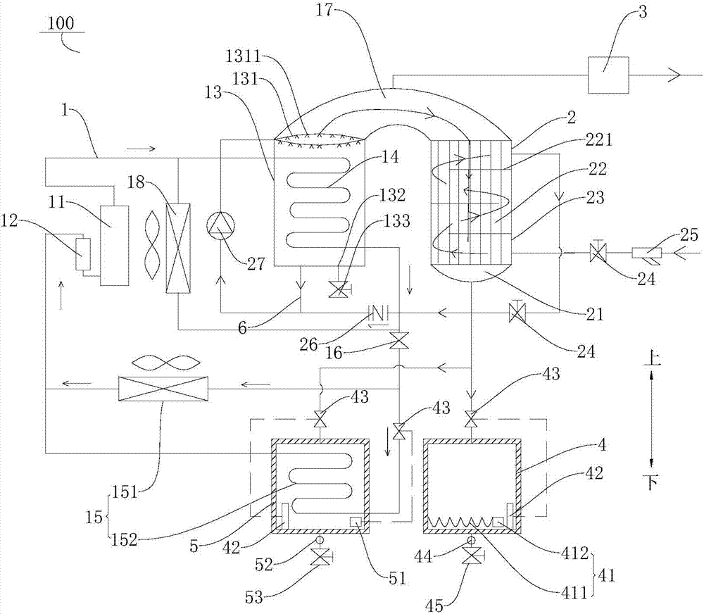
[0096] Such as figure 2As shown, the structure of this embodiment is substantially the same as that of Embodiment 1, wherein the same components use the same reference numerals, the only difference is that the air conditioning system 100 also includes a second condenser 18, the second condenser 18 and the first The condensers 14 are connected in parallel, whereby the refrigerant can be sufficiently condensed.

Embodiment 3

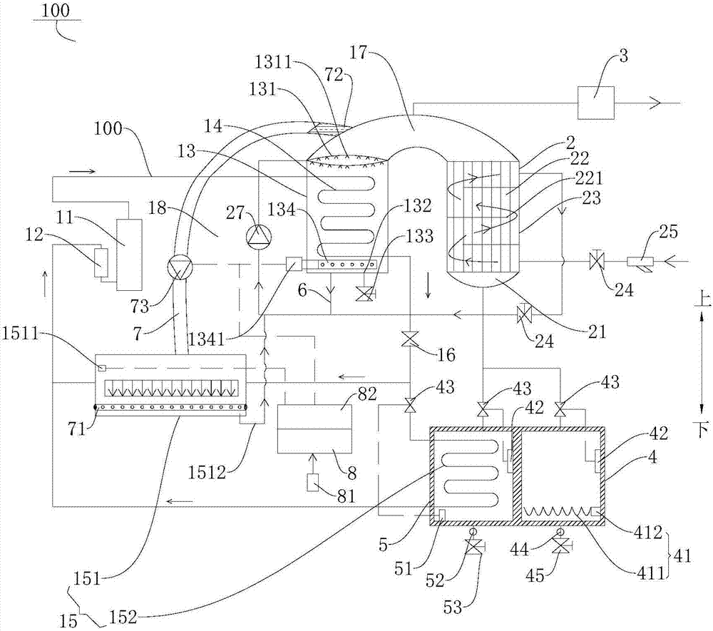
[0098] Such as image 3 As shown, the structure of the present embodiment is substantially the same as that of the first embodiment, wherein the same components use the same reference numerals, the only difference is that the air conditioning system 100 also includes a steam conduit 7, and one end of the steam conduit 7 passes through the The passage 17 communicates with the airflow passage 22, and the other end of the steam conduit 7 is close to the first evaporator 151 (wall-mounted air conditioner). The other end of the steam conduit 7 , that is, the end of the steam conduit 7 close to the first evaporator 151 is provided with a gas splitter 71 . The gas splitter 71 is located at the air outlet of the air conditioner. The gas splitter 71 is equipped with circular holes of uniform size to distribute the steam evenly. One end of the steam conduit 7 is provided with a steam filter 72, which can filter out the steam in the steam. Impurities, etc. The water vapor generated in ...


PUM


Abstract

The invention discloses an air conditioner system comprising a refrigerating circuit, a preheater, a vacuum pump, a first water tank and a bubbling machine. The refrigerating circuit comprises a condensing box, a first condenser and an evaporator. The first condenser is arranged in the condensing box. A refrigerant in the refrigerating circuit flows from the first condenser to the evaporator. A water storage trough, an airflow channel and a water flow channel are arranged in the preheater, and the airflow channel and the water flow channel are independent of each other. One end of the airflow channel communicates with the inside of the condensing box. The other end of the airflow channel communicates with the water storage trough. One end of the water flow channel communicates with a water source. The other end of the water flow channel communicates with the condensing box. The vacuum pump communicates with the inside of the condensing box. The first water tank communicates with the water storage trough. The bubbling machine is arranged at the bottom of the condensing box. According to the air conditioner system, normal refrigeration of the air conditioner system can be ensured, the problems of heat waste of the condenser, frequent replacement of a filter element of a direct drinking machine and poor water quality can also be solved, comprehensive utilization of energy is achieved, energy conservation and environment protection are achieved, and using is convenient.

Description

technical field [0001] The invention relates to the technical field of refrigeration, in particular to an air conditioning system. Background technique [0002] In the related art, the function of the air conditioner is relatively single, and generally only has the function of adjusting the indoor temperature. When cooling, the evaporator absorbs heat to lower the temperature in the room, while the heat released by the condenser is discharged to the atmosphere in the form of hot air, resulting in a large amount of heat waste. And while the air conditioner is cooling down, it will keep taking away the moisture in the room, making the indoor air very dry. If you turn on the air conditioner for a long time, you will feel dry throat and thirst. In addition, the condensed water produced by the air conditioner during operation It will be discharged to the outside through the drain pipe. Since the installer did not treat the drain pipe, people passing by downstairs will often be d...

Claims


Application Information

Patent Timeline
Patent Type & Authority Applications(China)
IPC IPC(8): F25B29/00
CPCF25B29/003
Inventor 魏留柱
Owner GD MIDEA AIR-CONDITIONING EQUIP CO LTD
Why Eureka
Eureka Blog
Learn More