Uniform distribution type pulsating flow generating device for vibration induction of elastic tube bundles inside heat exchanger

A technology of tube bundle vibration and generating device, which is applied in heat transfer modification, heat exchange equipment, lighting and heating equipment, etc. It can solve the problem of inability to achieve the expected vibration of enhanced heat exchange, inconsistent pulsating flow intensity and frequency, and stable flow and flow. It can improve the uneven vibration, avoid fatigue damage, and achieve the effect of uniform vibration.

Active Publication Date: 2015-12-09
SHANDONG UNIV
View PDF5 Cites 22 Cited by
  • Summary
  • Abstract
  • Description
  • Claims
  • Application Information

AI Technical Summary

Problems solved by technology

However, due to the top sealing structure of this device, there is a flow "dead zone" in the internal flow field, and the flow and flow stability of the fluid flowing into each branch pulsating tube are poor, and pulsating flow cannot be generated at the outlet of some pulsating tubes, and generated Inconsistent intensity and frequency of pulsating flow to achieve desired vibrations needed to enhance heat transfer

Method used


Image

  • Uniform distribution type pulsating flow generating device for vibration induction of elastic tube bundles inside heat exchanger
  • Uniform distribution type pulsating flow generating device for vibration induction of elastic tube bundles inside heat exchanger
  • Uniform distribution type pulsating flow generating device for vibration induction of elastic tube bundles inside heat exchanger

Examples


Embodiment Construction

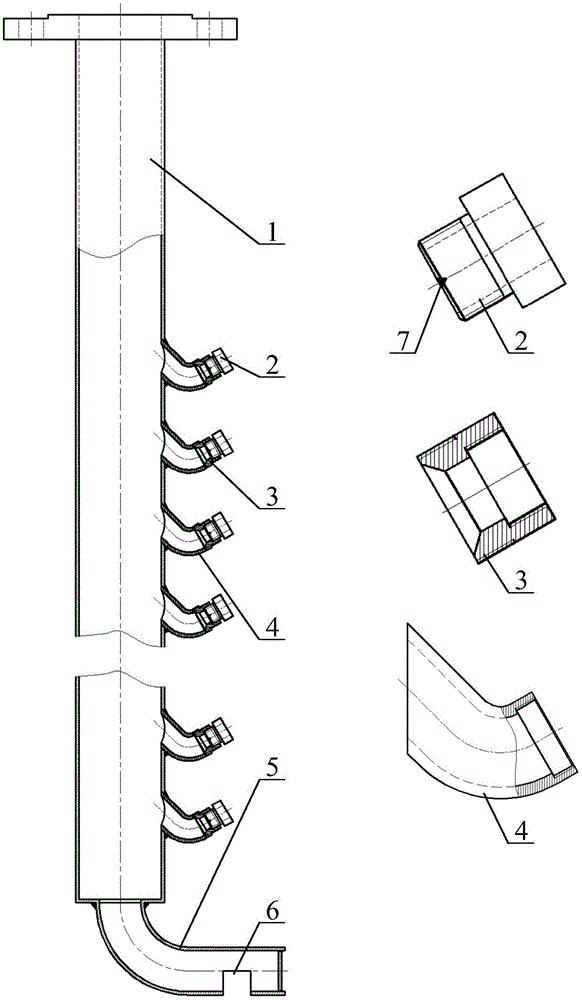
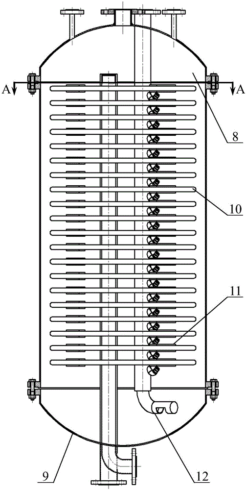
[0027] Such as figure 1 As shown, the uniformly distributed pulsating flow generating device 12 used for vibration induction of elastic tube bundles in heat exchangers of the present invention includes a vertical pipe 1, a branch elbow 4, a flow guide pipe 3, a pulsating flow pipe 2, and a shell-side water inlet pipe 5 and spoiler 7. Branch bends 4 are distributed outside the standpipe 1 , and the distances between adjacent branch bends 4 are consistent. One end of each branch elbow 4 is welded on the standpipe 1 and communicated with the standpipe 1 , and the other end is connected with a diversion pipe 3 connected with a pulsating flow pipe 2 . The axis included angle (bending angle) between the two curved sections in the branch elbow 4 is 75°-120°. The axis of the section connected to the vertical pipe 1 on the branch elbow 4 and the lower section of the vertical pipe axis 1 (on the axis of the vertical pipe at the intersection of the two axes (the intersection of the axi...


PUM


Abstract

A uniform distribution type pulsating flow generating device for vibration induction of elastic tube bundles inside a heat exchanger comprises a vertical pipe, branch bent pipes, guide pipes, pulsating flow pipes, turbulator bodies and a shell pass water inlet pipe. The branch bent pipes consistent in spacing are distributed on the vertical pipe, the guide pipes are connected to the corresponding branch bent pipes, the pulsating flow pipes are connected to the guide pipes, and the turbulator bodies are arranged on the pulsating flow pipes. The shell pass water inlet pipe is arranged at the bottom end of the vertical pipe. When the uniform distribution type pulsating flow generating device is used, one end of the uniform distribution type pulsating flow generating device is fixed to an upper seal head of the heat exchanger, and the other end of the uniform distribution type pulsating flow generating device is suspended at the bottom of the heat exchanger. The uniform distribution type pulsating flow generating device can generate uniform and consistent pulsating flow having certain frequency and strength at outlets of the pulsating flow pipes by controlling the flow of a fluid flowing into the vertical pipe, induces the elastic tube bundles inside the elastic tube bundle heat exchanger to vibrate evenly, can achieve expected vibration required for heat transfer strengthening of the elastic tube bundle heat exchanger and avoids fatigue failures of the tube bundles due to vibration.

Description

technical field [0001] The invention relates to a pulsating flow generating device used for vibration induction of elastic tube bundles in heat exchangers, and belongs to the technical field of vibration induction of elastic tube bundles in heat exchangers. Background technique [0002] As a general-purpose process equipment for heat exchange between different media, heat exchangers are widely used in petroleum, chemical, electric power, refrigeration and other industrial fields. The enhanced heat exchange technology of the heat exchanger strives to improve the heat exchange capacity of the heat exchanger to achieve the purpose of saving energy and reducing consumption. According to whether additional power is required, enhanced heat transfer technology can be divided into active enhanced heat transfer technology and passive enhanced heat transfer technology. Passive enhanced heat transfer technology is the focus of current research on enhanced heat transfer technology beca...

Claims


Application Information

Patent Timeline
Patent Type & Authority Applications(China)
IPC IPC(8): F28F13/10
Inventor 葛培琪季家东毕文波
Owner SHANDONG UNIV
Why Eureka
Try Eureka