Optical module

A technology of optical module and optical zone, which is applied in the field of optical communication, can solve the problems that light cannot be injected into the optical fiber, and light cannot be received, so as to achieve the effect of stabilizing the propagation direction and reducing the offset

Inactive Publication Date: 2015-12-09
HISENSE BROADBAND MULTIMEDIA TECH
View PDF5 Cites 4 Cited by
  • Summary
  • Abstract
  • Description
  • Claims
  • Application Information

AI Technical Summary

Problems solved by technology

For the optical module, this offset will cause the actual propagation path of the light to seriously deviate from the set path, so that the light cannot enter the optical fiber or the light cannot be received

Method used


Image

  • Optical module
  • Optical module
  • Optical module

Examples


Embodiment Construction

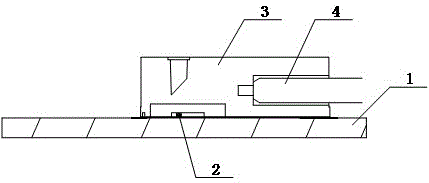
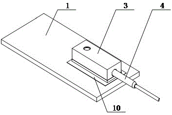
[0014] figure 1 It is a schematic structural diagram of an optical module provided by an embodiment of the present invention. like figure 1 As shown, the optical module provided by the embodiment of the present invention includes a circuit board 1, an optical transmitter / receiver 2, and a lens assembly 3, an optical fiber 4 is inserted into the lens assembly 3, and the light emitted by the optical transmitter / receiver 2, After the optical path is changed by the lens assembly 3, it enters the optical fiber 4. The optical transmitter / receiver 2 is located on the surface of the circuit board 1, and the optical transmitter / receiver 2 is generally fixedly connected to the circuit board 1 by SMT technology, and the lens assembly 3 is covered on the optical transmitter / receiver 2 Above, the light emitted by the light transmitter / light receiver 2 passes through the lens assembly 3, and its propagation direction changes.

[0015] The optical module not only has the function of light...


PUM


Abstract

The invention provides an optical module and belongs to the field of optical communication. The optical module comprises a circuit board, a light emitter/receiver and a lens assembly. The light emitter/receiver is arranged on the surface of the circuit board. The lens assembly covers the light emitter/receiver and changes transmission direction of light. The edge of the lens assembly is provided with a first metal layer. The surface of the circuit board is provided with a second metal layer. The first metal layer is connected with the second metal layer in a welded manner, so the lens assembly is fixed on the circuit board. After light passes the lens assembly, the transmission direction is changed. In addition, by wielding the first metal layer and the second metal layer, offset between actual installation position and preset installation position is reduced.

Description

technical field [0001] The invention relates to the field of optical communication, in particular to an optical module. Background technique [0002] The optical module that realizes the photoelectric conversion function is the core device in the field of optical communication. [0003] As an active device, the optical transmitter / receiver requires a circuit board to supply power for its light emission / reception. Due to the limitation of the connection mode between the circuit board and the optical transmitter / receiver, the light emission of the optical transmitter / receiver / The direction of received light is often inconsistent with the direction of light entering and exiting the optical fiber. Therefore, it is necessary to change the propagation direction of the light emitted by the optical transmitter / receiver to make the propagation direction of the light consistent with the direction of light entering and exiting the optical fiber. At the same time, the optical transmit...

Claims


Application Information

Patent Timeline
Patent Type & Authority Applications(China)
IPC IPC(8): G02B6/42
CPCG02B6/42G02B6/4204
Inventor 黄永亮刘旭霞
Owner HISENSE BROADBAND MULTIMEDIA TECH
Why Eureka
Try Eureka