Design method for damping coefficient of transverse shock absorber at the end of high-speed rail vehicle body

A technology for lateral shock absorbers and high-speed rails, which is applied in the fields of instrumentation, calculation, electrical and digital data processing, etc., can solve problems such as theoretical design methods that are not given a system, and difficulties in dynamic analysis and calculation.

Inactive Publication Date: 2018-01-16
SHANDONG UNIV OF TECH
View PDF3 Cites 0 Cited by
  • Summary
  • Abstract
  • Description
  • Claims
  • Application Information

AI Technical Summary

Problems solved by technology

However, according to the available information, it is very difficult to analyze and calculate the dynamics of the rail vehicle because it is a multi-degree-of-freedom vibration system. Most of the theoretical design methods are based on computer technology and multi-body dynamics simulation software SIMPACK or ADAMS / Rail to optimize and determine its size through solid modeling. Good dynamic performance, however, with the continuous increase of the speed of rail vehicles, people put forward higher requirements for the design of the damping coefficient of the lateral shock absorber at the end of the car body, the current design of the damping coefficient of the lateral shock absorber at the end of the car body The method cannot give a guiding innovation theory, and cannot meet the development of shock absorber design requirements under the condition of continuous speed-up of rail vehicles.

Method used


Image

  • Design method for damping coefficient of transverse shock absorber at the end of high-speed rail vehicle body
  • Design method for damping coefficient of transverse shock absorber at the end of high-speed rail vehicle body
  • Design method for damping coefficient of transverse shock absorber at the end of high-speed rail vehicle body

Examples


Embodiment Construction

[0067] The present invention will be further described in detail through an embodiment below.

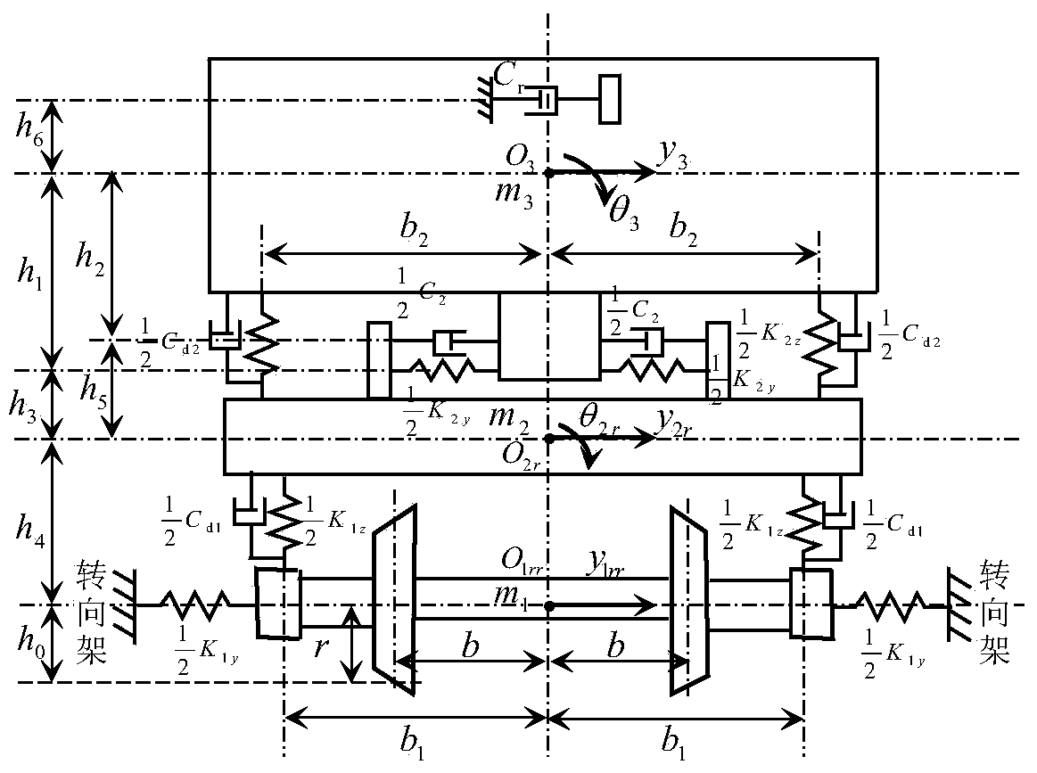
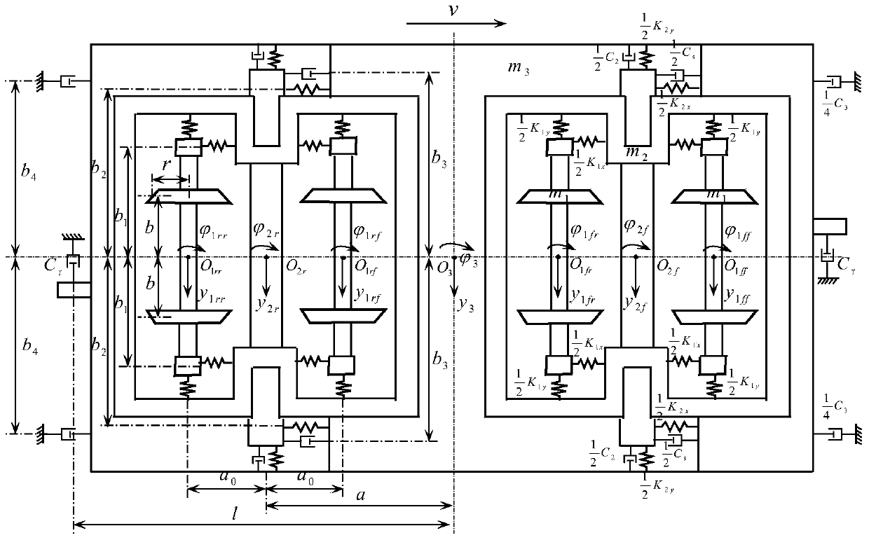
[0068] Four longitudinal shock absorbers at the end of the car body and one transverse shock absorber at the end of the car body are installed between two adjacent car bodies of a high-speed rail vehicle, that is, n=1, and the mass of a single car body is m 3 =63966kg, moment of inertia of shaking head Roll moment of inertia J 3θ =77200kg.m 2 ; Mass of each bogie frame m 2 =2758kg, Moment of inertia of shaking head Roll moment of inertia J 2θ =2212kg.m 2 ; the mass m of each round pair 1 =1721kg, Moment of inertia of shaking head Axle weight of each wheel W=150000N; lateral creep coefficient f of each wheel pair 1 =16990000N, longitudinal creep coefficient f 2 =16990000N; The longitudinal positioning stiffness K of each wheel set 1x =13.739×10 6 N / m, lateral positioning stiffness K 1y =4.892×10 6 N / m; the vertical equivalent stiffness K of the unilateral primary susp...


PUM


Abstract

The invention relates to a design method for the damping coefficient of a transverse shock absorber at the car body end of a high-speed rail vehicle, and belongs to the technical field of high-speed rail vehicle suspension. The present invention establishes a 17-degree-of-freedom lateral vibration optimization design simulation model of a rail vehicle, takes track direction irregularity and horizontal irregularity as input excitations, and takes the minimum root mean square value of the vibration acceleration of the rolling motion of the car body as the design target to optimize The optimal damping coefficient of the transverse shock absorber at the end of the car body is obtained by design. Through the design example and SIMPACK simulation verification, it can be seen that this method can obtain accurate and reliable damping coefficient values ​​of the lateral shock absorbers at the end of the car body, and provide a reliable design for the design of the damping coefficient of the lateral shock absorbers at the end of the high-speed rail vehicle method. Using this method can not only improve the design level of the suspension system of high-speed rail vehicles, but also improve the safety and stability of vehicles; at the same time, it can also reduce product design and test costs, and enhance the international market competitiveness of my country's rail vehicles.

Description

technical field [0001] The invention relates to a high-speed rail vehicle mount, in particular to a design method for the damping coefficient of a transverse shock absorber at the end of a high-speed rail vehicle body. Background technique [0002] The lateral shock absorber at the end of the car body is installed between two adjacent car bodies of the articulated or bogie-type high-speed rail vehicle, which can effectively control the sway of the car body and significantly increase the integrity and stability of the vehicle. However, according to the available information, it is very difficult to analyze and calculate the dynamics of the rail vehicle because it is a multi-degree-of-freedom vibration system. Most of the theoretical design methods are based on computer technology and multi-body dynamics simulation software SIMPACK or ADAMS / Rail to optimize and determine its size through solid modeling. Good dynamic performance, however, with the continuous increase of the sp...

Claims


Application Information

Patent Timeline
Patent Type & Authority Patents(China)
IPC IPC(8): G06F17/50
Inventor 周长城于曰伟赵雷雷
Owner SHANDONG UNIV OF TECH
Why Eureka
Try Eureka