
A Ridge Waveguide Power Splitter for Ridge Waveguide Slot Antenna Array

A technology of slot antenna and ridge waveguide, which is applied in the field of power division and synthesis network, can solve the problems of narrowing the gap, difficulty in processing, limited power division ratio of the port, etc., and achieve the effects of small fluctuation in the band, high transmission efficiency and easy processing

Active Publication Date: 2018-03-02
ANHUI SUN CREATE ELECTRONICS
View PDF3 Cites 0 Cited by
  • Summary
  • Abstract
  • Description
  • Claims
  • Application Information

AI Technical Summary

Problems solved by technology

[0003] Due to the reduction of the size of the ridge waveguide structure and the asymmetry of its own shape, the complexity of the synthesis network of the ridge waveguide dual-polarized antenna array is also greatly increased. Especially in the millimeter wave band, the size of the ridge waveguide synthesis network is smaller, which gives Processing brings certain difficulties
In the combined ridge waveguide network of the same layer, the electric field of the ridge waveguide is mainly concentrated between the ridge and the metal wall, and the change in the same layer is continuous. There are few relevant materials about the ridge waveguide power splitter. The ridge waveguide power divider adopts a design method similar to that of a rectangular waveguide power divider, and the feeding port matching is obtained by adding a metal diaphragm on the common wall of the two ports at the T-shaped position of the ridge waveguide power divider, and adjusting the metal film The size and position of the chip can also obtain different port power ratios to a certain extent, but the port power ratios that can be adjusted by this design method are very limited. In addition, the actual processing is limited by the size of the milling cutter, Due to the requirements of processing accuracy and power capacity, the gap between the metal diaphragm and the metal wall at the T-shaped position cannot be infinitely reduced, especially in the millimeter wave band, this effect will be more prominent
[0004] In summary, the ridge waveguide dual-polarization slot antenna has many application backgrounds and application advantages. Correspondingly, the complexity of the synthesis network of the ridge waveguide dual-polarization slot antenna is also greatly increased. For the ridge waveguide power splitter, by adjusting the ridge waveguide The size and position of the T-shaped position diaphragm of the power divider has a very limited ability to obtain different power division ratios between the two ports, and cannot meet the requirements of dual-port high power division ratios, so it cannot meet the millimeter-wave ridge waveguide with special amplitude weighting requirements Dual-polarization slot array, so a new type of ridge waveguide power divider is urgently needed to achieve a high power ratio signal output under the premise of the limitation of space structure and processing technology

Method used


Image

  • A Ridge Waveguide Power Splitter for Ridge Waveguide Slot Antenna Array
  • A Ridge Waveguide Power Splitter for Ridge Waveguide Slot Antenna Array
  • A Ridge Waveguide Power Splitter for Ridge Waveguide Slot Antenna Array

Examples


Embodiment 1

[0028] The central operating frequency of the ridge waveguide power divider used in the ridge waveguide slot antenna array in this embodiment is 35Ghz, and the in-band operating frequency is 34.5Ghz˜35.5Ghz.

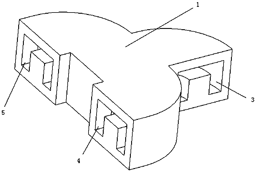
[0029] see figure 1 , the ridge waveguide power divider used for the ridge waveguide slot antenna array is a single ridge waveguide power divider, which has a feed port 3, a first sub-port 4 and a second sub-port 5, wherein the feed port 3 is located on one side, so The first branch port 4 and the second branch port 5 are located side by side on the other side.

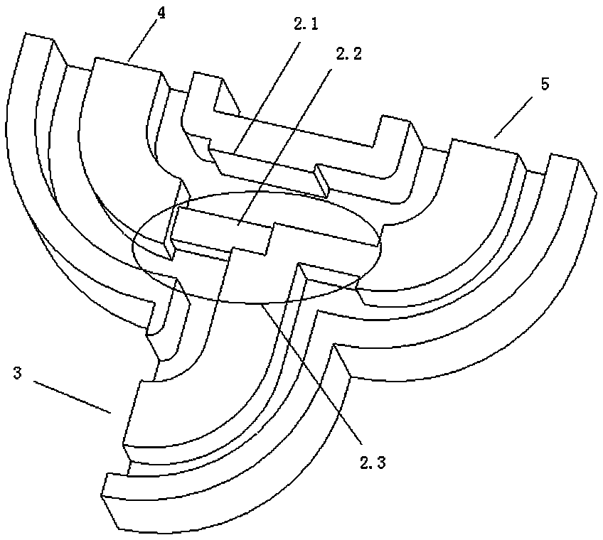
[0030] see figure 2 , the inner end of the ridge of the feed port 3, the inner end of the ridge of the first sub-port 4 and the inner end of the ridge of the second sub-port 5 are connected by a T-shaped block 2.3, wherein the top two ends of the T-shaped block 2.3 Connect the inner end of the ridge of the first sub-port 4 and the inner end of the ridge of the second sub-port 5 respectively, the bottom end of...

Embodiment 2

[0037] In this embodiment, the central working frequency is 17.6Ghz, and the in-band working frequency is 17.3Ghz~17.8Ghz.

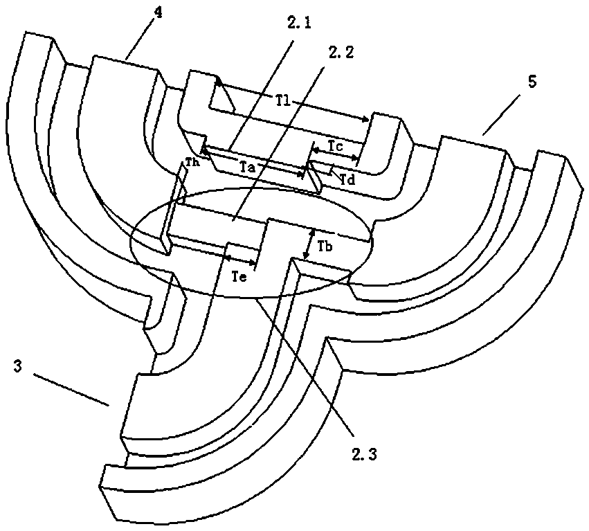
[0038] The structure of this embodiment is the same as that of Embodiment 1, see the main structure diagram Figure 1~Figure 5 , Ridge waveguide cross-sectional length Ra = 6mm, cross-sectional height Rb = 4mm, ridge width Rw = 2.8mm, ridge height Rh = 2.6mm. The metal wall thickness of the middle transformation section of the T-shaped block 2.3 is Tb=1.4mm, the transformation section 2.2 close to the first branch port 4 is lower than the height of the ridge Th=1.1mm, and the distance from the edge of the single ridge to the feeder port 3 is Te=1.4m. The lengths of the transformation sections Tf and Tg on both sides of the T-shaped block 2.3 are 4.2mm and 4.4mm respectively, and the length of the transformation section on one side is Tk=4mm. Ta and Td are 4.5mm and 0.3mm respectively, metal diaphragm 2.1 distance Tc=2.225mm from the metal wall of the se...


PUM


Abstract

The invention relates to a ridge waveguide power splitter used for a ridge waveguide slot antenna array. This ridge waveguide power splitter is a single ridge waveguide power splitter, which has a feed port, a first sub-port and a second sub-port, wherein the feed port is located on one side, and the first sub-port and the second sub-port are located side by side on the other side. Side; the inner end of the ridge of the feed port, the inner end of the ridge of the first sub-port and the inner end of the ridge of the second sub-port are connected by a T-shaped block, and the corresponding ridge waveguide power divider on the top of the T-shaped block There is a metal diaphragm on the common inner wall of the device; under the condition of very limited space size, the present invention can realize a power split ratio of more than 4:1 between the two ports, and the transmission efficiency is more than 99.9%, which solves the problem of ridge waveguide bipolar It is a major problem in the design of the synthesis network in the slotted array, and realizes the requirement of diversity weighting of the power division network in the ridge waveguide dual-polarization antenna, which is very suitable for layout and extension in various ridge waveguide synthesis networks.

Description

technical field [0001] The invention relates to a power division and synthesis network of a ridge waveguide slot array, especially the application in a double-polarized ridge waveguide slot array. The invention can be widely applied to the synthesizing network of the ridge waveguide slot antenna array, especially for the ridge waveguide synthesizing network with compact space and large port power division ratio. Background technique [0002] Due to the advantages of high efficiency and good structural strength, waveguide slot antennas are widely used in radar and various communication fields. With the increasingly higher requirements for feature extraction and the limitation of communication bandwidth due to the shortage of frequency resources, the demand for dual-polarized antennas is becoming more and more common, and dual-polarized waveguide slot antennas have been widely used. However, in some occasions where there are strict requirements on the size and weight of the d...

Claims


Application Information

Patent Timeline
Patent Type & Authority Patents(China)
IPC IPC(8): H01P5/12
Inventor 赵继明胡卫东吴文娟季宏红朱小三
Owner ANHUI SUN CREATE ELECTRONICS
Learn More