Housing assembly and connector

A technology of housing assembly and connector, applied in the direction of connection, parts of connection device, electrical components, etc., can solve the problems of connection failure, canted coil spring can not play the role of locking, anti-loosening, disengagement, etc., to ensure reliability and security, the effect of simplifying the internal structure

Active Publication Date: 2015-12-09
CHINA AVIATION OPTICAL-ELECTRICAL TECH CO LTD
View PDF6 Cites 16 Cited by
  • Summary
  • Abstract
  • Description
  • Claims
  • Application Information

AI Technical Summary

Problems solved by technology

[0005] When this multi-latch mechanism is used in an environment with severe vibration or instantaneous impact, once the second connector assembly receives an instantaneous impact force, it is easy to overcome the force of the limit spring and move toward the first connector housing, so that Once it moves to the position where the canted coil spring slides into the groove of the secondary pin, the canted coil spring cannot play the role of locking and anti-loosening, and the second connector assembly will be connected from the first connection under the elastic force of the limit spring. out of the connector assembly, resulting in connection failure

Method used


Image

  • Housing assembly and connector
  • Housing assembly and connector
  • Housing assembly and connector

Examples


Embodiment 1

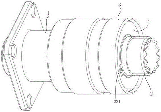
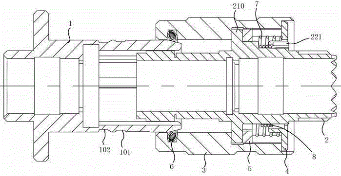
[0032] Embodiment 1 of the connector of the present invention: includes a housing assembly, defines the front end of the housing assembly as a plug-in end 10 for plugging and mating with the adapter connector 1, and the housing assembly includes a canted coil spring at the front end The locking cap 3 is provided with a canted coil spring installation groove 36 on the inner peripheral surface of the front end of the locking cap 3 , and the canted coil spring 6 is installed in the canted coil spring installation groove 36 .

[0033] The housing assembly also includes a connector housing 2 that extends forward and backward. The locking cap 3 is rotatably sleeved on the outer periphery of the connector housing 2, defining the front end of the connector housing 2 as a plug-in end, and the connector housing is plugged in There is an annular space for axially inserting the plug-in end of the adapter connector 1 between the end and the lock cap 3 . The front end of the adapter connect...

Embodiment 3

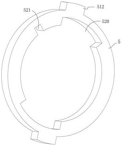
[0050] Embodiment 3 of the connector of the present invention: the difference from Embodiment 1 is that there is no inner retaining ring between the connector housing and the locking cap, and the torsion spring acts on the connector housing and the locking cap , the two ends of the return spring press against the limit retaining ring and the convex ring of the connector housing respectively. At this time, because there is no retaining ring chute of the inner ring retaining ring, the rotation limit of the locking cap relative to the connector housing is limited. , it cannot be accurately judged at what position the bump on the connector housing is opposite to the straight groove of the lock cap in the circumferential direction, then it is necessary to artificially judge the bump on the connector housing when the lock cap is unlocked The position when it is opposite to the straight groove of the locking cap in the circumferential direction.

[0051] The embodiment of the housing...


PUM


Abstract

The invention provides a housing assembly and a connector. The connector comprises a locking cap and a connector housing, wherein the front end of the locking cap is provided with a canted coil spring. The locking cap is rotatingly disposed on the connector housing in a sleeve manner, and the rear end of the locking cap is provided with a peripheral chute and an axial chute, wherein the axial chute is communicated with the peripheral chute and extends backwards from the peripheral chute. The connector housing is provided with a sliding block which can rotate in the peripheral chute relative to the locking cap, and also can move axially in the axial chute relative to the locking cap. The housing assembly also comprises an elastic part which provides a clockwise torque for the locking cap. The housing assembly also comprises a peripheral limiting structure which is used for limiting the clockwise rotating limit of the locking cap when the sliding block is located in the peripheral chute. When the locking cap is located at a limit position of clockwise rotation, the sliding block is staggered with the axial chute in a peripheral direction. The connector is reliable in locking, and is convenient to use.

Description

technical field [0001] The invention relates to a shell assembly and a connector. Background technique [0002] With the rapid development of power systems, the importance of electrical connectors has gradually become prominent. As a basic conductive connection element, the electrical connector will directly affect the reliability and stability of the conductive connection whether its performance is good or not. The main function of the connector anti-loosening structure is to prevent the connector from loosening and separating during use, so as to ensure reliable contact between the internal contacts of the connector. [0003] For example, the Chinese invention patent with application publication number CN103166050A and application publication date of 2013.6.19 discloses a multi-latch mechanism and related methods. This multi-latch mechanism mainly includes a first connector assembly and a second connector assembly. , wherein the first connector assembly has an insertion ...

Claims


Application Information

Patent Timeline
Patent Type & Authority Applications(China)
IPC IPC(8): H01R13/639H01R13/514
Inventor 杜博文李强
Owner CHINA AVIATION OPTICAL-ELECTRICAL TECH CO LTD
Why Eureka
Try Eureka