Moving-coil loudspeaker

A moving coil loudspeaker and voice coil technology, applied in the direction of sensors, electrical components, etc., can solve the problems of the magnetic performance attenuation of the driving magnet, the reduction of the magnetic performance of the driving magnet, and the demagnetization, so as to reduce the degree of magnetic attenuation and reduce the effect of magnetic attenuation. , the effect of improving stability

Active Publication Date: 2015-12-09
NINGBO TONWEL AUDIO
View PDF5 Cites 1 Cited by
  • Summary
  • Abstract
  • Description
  • Claims
  • Application Information

AI Technical Summary

Problems solved by technology

[0003] It can be seen that during the working process of the speaker, the voice coil is vibrating alternately, so the friction between the voice coil and the air, and the friction between the voice coil and the driving magnet will generate a certain amount of heat. If it cannot be discharged in time, the drive magnet will have a thermal demagnetization effect, which will eventually lead to a decrease in the magnetic performance of the drive magnet or complete demagnetization
Especially in high-power speakers, the amplitude and vibration frequency of the voice coil are relatively high, so the rate of heat generation is far greater than the rate of speaker heat dissipation, which limits the continuous working time of high-power speakers. However, the long-term continuous use of the above-mentioned existing high-power loudspeaker by the operator will cause the magnetic performance of the driving magnet to attenuate, thereby reducing the service life of the loudspeaker.
This is the problem that the high-power loudspeaker in the prior art is easily damaged after long-term continuous use

Method used


Image

  • Moving-coil loudspeaker
  • Moving-coil loudspeaker

Examples


Embodiment Construction

[0015] The present invention will be further described below in conjunction with the accompanying drawings and specific embodiments.

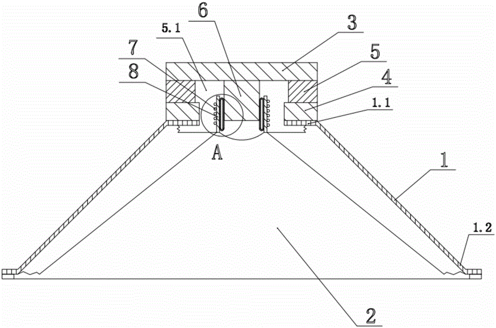
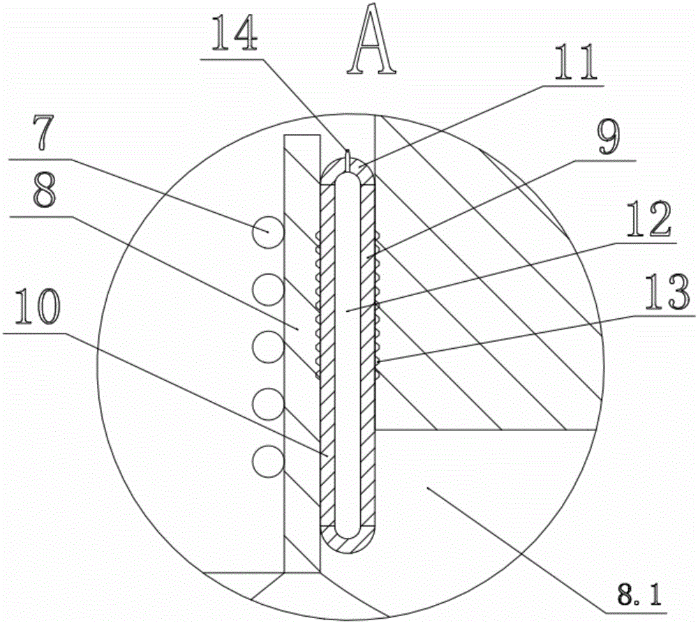
[0016] The present invention provides a moving coil loudspeaker, which includes a pot frame 1, a paper cone 2, a first magnetically conductive plate 3, a second magnetically conductive plate 4, a driving magnet 5, a magnetically conductive core post 6, a voice coil 7 and a voice coil Guide tube 8, the drive magnet 5 is clamped between the first magnetically conductive plate 3 and the second magnetically conductive plate 4, the second magnetically conductive plate 4 is fixed to the small mouth end 1.1 of the frame 1, and the voice coil 7 is wound on The outside of the voice coil guide cylinder 8, together with the voice coil guide cylinder 8, is accommodated in the center hole 5.1 of the driving magnet 5, one end of the voice coil guide cylinder 8 is fixed to one end of the paper cone 2, and the paper cone 2 is erected on the basin frame 1 , and...


PUM


Abstract

The invention discloses a moving-coil loudspeaker. The loudspeaker comprises a basin frame, a paper basin, a first magnetic conductive plate, a second magnetic conductive plate, a driving magnet, a magnetic conductive core column, a sound coil and a sound coil guide cylinder. The driving magnet is clamped between the first magnetic conductive plate and the second magnetic conductive plate. The second magnetic conductive plate is fixed on the basin frame. The sound coil is wound outside the sound coil guide cylinder. The sound coil and the sound coil guide cylinder are arranged in a central hole of the driving magnet. One end of the magnetic conductive core column is fixed on the first magnetic conductive plate, and the other end is inserted in a central through hole of the sound coil guide cylinder. The magnetic conductive core column is in sliding fit with the sound coil guide cylinder. The loudspeaker is characterized in that a lubricating mechanism which is used for reducing friction force between the outer side wall of the magnetic conductive core column and the inner side wall of the sound coil guide cylinder is arranged between the magnetic conductive core column and the sound coil guide cylinder. According to the invention, heat energy generated by friction in the vibration sounding process of the sound coil is reduced, so time for continuous work of the loud speaker is increased and service lifetime of the loudspeaker is extended.

Description

technical field [0001] The invention relates to the technical field of electro-acoustic transducers, in particular to a dynamic-coil loudspeaker. Background technique [0002] Dynamic speakers are also called dynamic speakers. Its working principle is based on Faraday's law. When a current-carrying conductor passes through a magnetic field, it will receive an electromotive force. Its direction conforms to Fleming's left-hand rule. The force, current, and magnetic field are perpendicular to each other. The magnetic flux density is directly proportional. When the voice coil is input with alternating audio current, the voice coil is subjected to an alternating driving force to produce alternating motion, which drives the paper cone to vibrate, and repeatedly pushes the air to produce sound. [0003] It can be seen that during the working process of the speaker, the voice coil is vibrating alternately, so the friction between the voice coil and the air, and the friction betwee...

Claims


Application Information

Patent Timeline
Patent Type & Authority Applications(China)
IPC IPC(8): H04R9/06H04R9/02
Inventor 李自全
Owner NINGBO TONWEL AUDIO
Why Eureka
Try Eureka