Bumper for a motor vehicle

A technology for motor vehicles and bumpers, which is applied to bumpers, vehicle parts, vehicle safety arrangements, etc., and can solve problems such as high material costs

Inactive Publication Date: 2015-12-09
THYSSENKRUPP STEEL EURO AG
View PDF12 Cites 2 Cited by
  • Summary
  • Abstract
  • Description
  • Claims
  • Application Information

AI Technical Summary

Problems solved by technology

Although these bumpers have a relatively low weight, the

Method used


Image

  • Bumper for a motor vehicle
  • Bumper for a motor vehicle
  • Bumper for a motor vehicle

Examples


Embodiment Construction

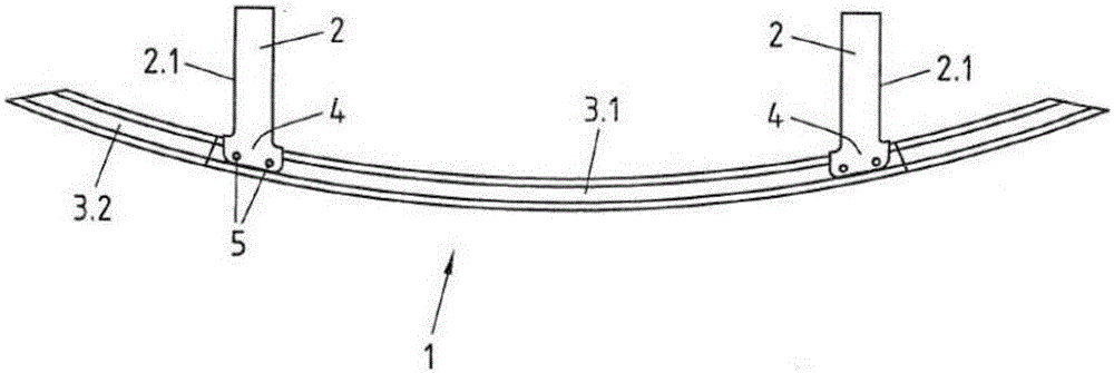
[0028] figure 1 A bumper 1 for a motor vehicle is shown, which bumper is in particular intended as a front bumper.

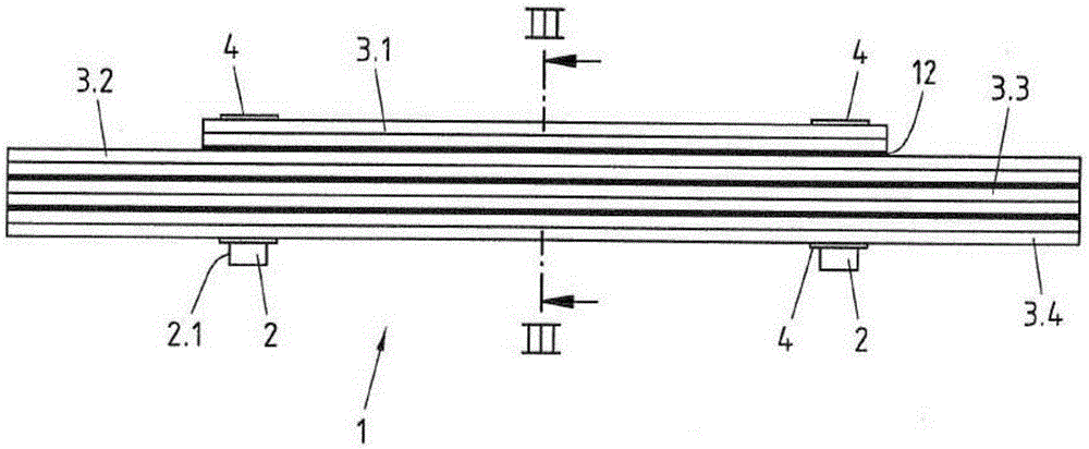
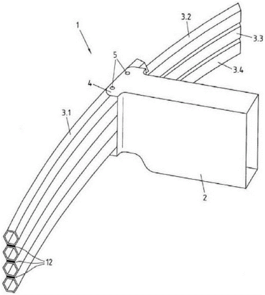
[0029] The bumper 1 comprises two deformation bodies 2 which can also be referred to as crash boxes. The longitudinal axis or center of the deformation body is oriented substantially parallel to the direction of travel of the motor vehicle, ie the longitudinal direction. The deformation body 2 is fastened to a longitudinal frame or other part of the vehicle body. In the exemplary embodiment shown, the hollow deformation body 2 has a substantially rectangular cross-sectional profile. Alternatively, the deformation body can also be designed, for example, with an oval or circular cross-sectional profile.

[0030] Furthermore, the bumper 1 comprises at least three crossbeams 3.1, 3.2, 3.3 arranged parallel to each other one above the other and the crossbeams 3.1, 3.2, 3.3 are connected to the deformation body 2 by suitable fastening means. Each beam 3.1, 3.2, 3....


PUM

PropertyMeasurementUnit
Tensile strengthaaaaaaaaaa

Abstract

The invention relates to a bumper (1) for a motor vehicle, particularly a front bumper, comprising at least two deformation elements (2) which are spaced apart from one another and whose central or longitudinal axes are aligned, when mounted, substantially parallel to the direction of travel of said motor vehicle, as well as a plurality of cross-members (3.1, 3.2, 3.3, 3.4) which have a closed profile and are arranged one above the other and connected to said deformation elements (2). In order for the bumper to provide relatively high resistance at a low weight such that in the event of a collision at speeds lower than 20 km/h, rearward displacement of the cross-member is limited in a targeted manner and movement of the bumper (1) upwards or downwards caused by the bumper of the other vehicle implicated in the collision is prohibited, said cross-members (3.1, 3.2, 3.3, 3.4) are formed from a group of at least three cross-members, each of these cross-members (3.1, 3.2, 3.3, 3.4) of the group having an at least five-cornered cross-sectional profile.

Description

technical field [0001] The invention relates to a bumper for a motor vehicle, in particular a front bumper, having at least two deformation bodies spaced apart from each other and having their longitudinal axes or centers substantially parallel in the mounted state and a plurality of cross members Oriented in the direction of travel of the motor vehicle, and the plurality of cross members have a closed profile and are arranged one above the other and are connected to deformation bodies (so-called crash boxes). Background technique [0002] Such a bumper is known from DE102004056956B4. Known bumpers have at least two round tubes as cross members, which are arranged vertically one above the other and are connected to each other between the side frames (crash boxes) by means of plate-like brackets. In this case, the bracket is provided on the front side of the tube and is welded to said tube. The bracket has upper and lower curved ends matching the shape of the tube. The tub...

Claims


Application Information

Patent Timeline
IPC IPC(8): B60R19/12B60R19/18
CPCB60R19/12B60R19/18B60R2019/1826B60R19/03B60R19/34
Inventor 马丁·基宾罗尔夫·彼得·勒特格马库斯·策纳克
Owner THYSSENKRUPP STEEL EURO AG
Why Eureka
Try Eureka