Intelligent card cleaning device capable of cleaning upper cleaning wheels and lower cleaning wheels
A cleaning device and smart card technology, applied in cleaning methods and appliances, cleaning methods using tools, chemical instruments and methods, etc., can solve the problems of cleaning rollers that cannot be cleaned, poor cleaning effect of cards, etc., and achieve the effect of improving conveying efficiency
- Summary
- Abstract
- Description
- Claims
- Application Information
AI Technical Summary
Problems solved by technology
Method used
Image
Examples
Embodiment 1
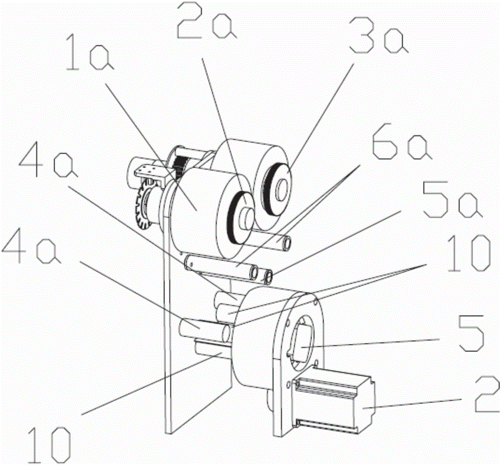
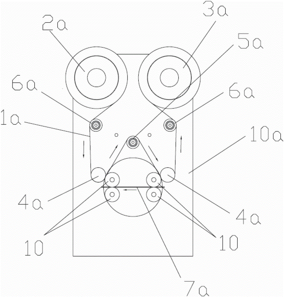
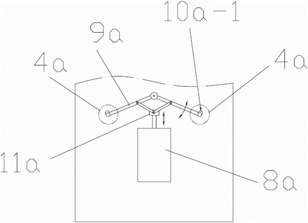
[0038] see Figure 1 ~ Figure 4 The smart card cleaning device that can clean the upper and lower cleaning rollers of the present invention includes a frame 10a, a dust removal mechanism on the card surface, and a cleaning belt conveying mechanism, wherein the cleaning belt conveying mechanism includes a cleaning belt 1a, an unused cleaning belt rewinding wheel 2a , Used cleaning belt rewinding wheel 3a, guide wheel group and rewinding power mechanism.
[0039] The card surface dust removal mechanism includes a fixed frame 1, two sets of cleaning rollers, an overturning power mechanism for driving the two sets of cleaning rollers to rotate as a whole, and a card conveying power for driving the rotation of each cleaning roller 10 in the two sets of cleaning rollers. mechanism, each group of cleaning rollers includes two pairs of cleaning rollers 10, and the card conveying power mechanism is arranged on the turning part of the turning power mechanism; the rotation center of the ...
Embodiment 2
[0054] The difference between this embodiment and embodiment 1 is that in this embodiment:
[0055] see Figure 8, the transmission mechanism includes four transmission gears 15 and a synchronous belt transmission mechanism 16, wherein each cleaning roller 10 is coaxially connected with a transmission gear 15 respectively, and two transmission gears 15 in a group of cleaning rollers are meshed; The main shaft of the card feeding motor 5 is connected with one of the cleaning rollers 10 in one group of cleaning rollers to form a power roller, which cleans with one of the other cleaning rollers through the synchronous belt transmission mechanism 16. Roller 10 is connected.
Embodiment 3
[0057] The difference between this embodiment and Embodiment 1 is that in the compression control mechanism of this embodiment:
[0058] see Figure 9 ~ Figure 12 , the transmission mechanism includes two rotating arms 11a, one end of the two rotating arms 11a is connected to a cleaning belt pressing wheel 4a, the middle part is connected to the frame 10a through a rotatable structure, and the other end is provided with some gears that mesh with each other 11a-1; the power mechanism is a rotation drive mechanism that pushes one of the rotation arms 11a to rotate.
[0059] see Figure 9 ~ Figure 12 , the power mechanism is composed of an electromagnet 12a, the outer end of the armature 13a of the electromagnet 12a is connected to one of the rotating arms 11a through a swing rod 14a, and a spring 15a is provided on the armature 13a. Its working principle is: under normal conditions, the electromagnet 12a is in a de-energized state, under the action of the spring 15a, the armat...
PUM
 Abstract
Description
Claims
Application Information
 - R&D
- Intellectual Property
- Life Sciences
- Materials
- Tech Scout
- Unparalleled Data Quality
- Higher Quality Content
- 60% Fewer Hallucinations
Browse by: Latest US Patents, China's latest patents, Technical Efficacy Thesaurus, Application Domain, Technology Topic, Popular Technical Reports.
© 2025 PatSnap. All rights reserved.Legal|Privacy policy|Modern Slavery Act Transparency Statement|Sitemap|About US| Contact US: help@patsnap.com


