Automatic wire arranging welding device

A welding device and automatic wiring technology, applied in welding equipment, resistance welding equipment, metal processing equipment, etc., can solve problems such as difficulty in ensuring welding quality, increasing welding difficulty, and complicated manufacturing process

Active Publication Date: 2015-12-16
GUANGDONG HWASHI TECH INC
View PDF5 Cites 10 Cited by
  • Summary
  • Abstract
  • Description
  • Claims
  • Application Information

AI Technical Summary

Problems solved by technology

There are great differences in welding products involved in different application fields. In technical fields such as condensers that require multi-sided wiring welding, how to realize automatic wiring welding is the key welding technology in these fields. It can not only affect welding quality, but also improve welding quality. The primary consideration of efficiency. The current common condenser structure is to weld a number of evenly arranged heat dissipation lines on both sides of the coolant pipe. There are a number of iron wires or steel wires closely welded on both sides of the condenser as a heat dissipatio

Method used


Image

  • Automatic wire arranging welding device
  • Automatic wire arranging welding device
  • Automatic wire arranging welding device

Examples


Embodiment Construction

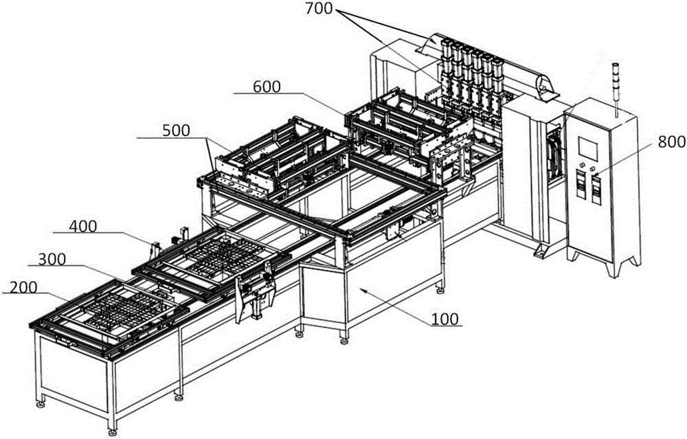
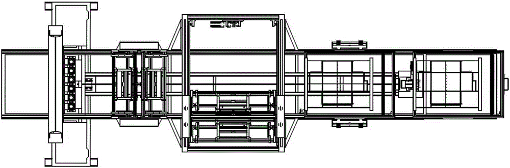
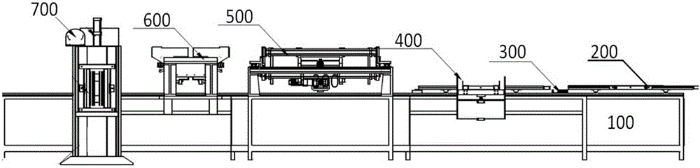
[0052] The technical solutions of the present invention will be described in detail below in conjunction with the accompanying drawings, so that those skilled in the art can understand the present invention more clearly, but the protection scope of the present invention is not limited thereby.

[0053] As attached figure 1 Attached image 3 As shown, the automatic wiring welding device of the present invention as a whole includes an automatic welding system 700, a horizontal wiring system 600, a vertical wiring system 500, a support main body 100, a material rack lifting system 400, a material rack moving system 300, a welding material rack 200 and Control system 800. The bracket body 100 serves as a support frame for the entire device. A material rack lifting system 400, a vertical wiring system 500, and a horizontal wiring system 500 are sequentially arranged on the bracket body 100 along the length direction of the bracket body 100 (from front to back). Wiring system 600 and a...


PUM


Abstract

The invention provides an automatic wire arranging welding device. The automatic wire arranging welding device comprises an automatic welding system, a wire arranging system, a support main body, a material rack lifting system, a material rack moving system, a welding material rack and a control system. The automatic welding system, the wire arranging system, the material rack lifting system, the material rack moving system, the welding material rack and the control system are all arranged on the support main body. The material rack lifting system is located on the front portion of the support main body. The automatic welding system is located on the rear portion of the support main body. The wire arranging system is located between the material rack moving system and the automatic welding system. The material rack moving system is arranged in the support main body and capable of driving the welding material rack to move forwards and backwards on the support main body. The control system is connected with the automatic welding system, the wire arranging system, the material rack lifting system and the material rack moving system, and controls the automatic welding system, the wire arranging system, the material rack lifting system and the material rack moving system. According to the automatic wire arranging welding device, the support main body, the welding material rack, the wire arranging system, the moving system and the automatic welding system are all designed innovatively, so that the whole welding device is capable of conducting the automatic wire arranging welding effectively and in high quality, and the device can be widely popularized in the technical field of welding, so that the market prospects are very broad.

Description

Technical field [0001] The invention relates to the field of welding technology, and more specifically to an automatic wiring welding device. Background technique [0002] With the increasing demand for welding and the development of welding technology, automatic welding has gradually become a trend. The use of electronic control systems to realize automatic control of the welding process has become the mainstream development direction in the current welding technology field. There are big differences in welding products involved in different application fields. In technical fields that require multi-sided wiring welding such as condensers, how to realize automatic wiring welding is a key welding technology in these fields, which can not only affect the quality of welding, but also improve welding. The primary consideration for efficiency, the current common condenser structure is to weld several evenly arranged heat dissipation lines on both sides of the coolant tube. The coolan...

Claims


Application Information

Patent Timeline
IPC IPC(8): B23K11/00B23K11/36
CPCB23K11/002B23K11/36
Inventor 丁小生
Owner GUANGDONG HWASHI TECH INC
Why Eureka
Try Eureka