Automatic screw locking machine

An automatic locking screw machine and screw technology, applied in metal processing equipment, metal processing, manufacturing tools, etc., can solve the problems of inclined inner side walls and stuck between the inner side walls of the suction end, sliding teeth, floating locks, etc.

Active Publication Date: 2015-12-16
桐乡市建春塑业股份有限公司
View PDF6 Cites 5 Cited by
  • Summary
  • Abstract
  • Description
  • Claims
  • Application Information

AI Technical Summary

Problems solved by technology

But usually, because the size of the part of the suction end that accommodates the screw is slightly larger than the size of the screw, when the screw enters the suction end, it may be inclined relative to the inn...

Method used


Image

  • Automatic screw locking machine
  • Automatic screw locking machine
  • Automatic screw locking machine

Examples


Embodiment Construction

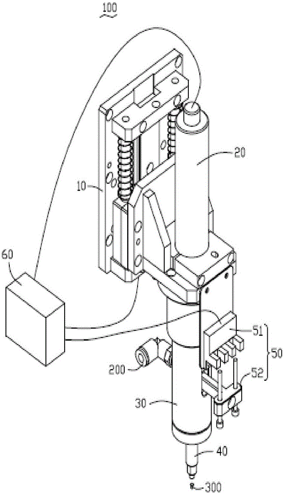
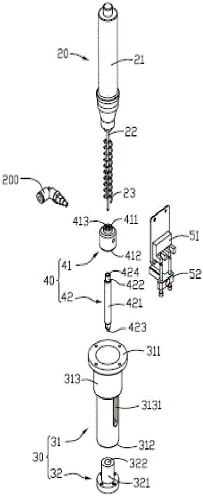
[0017] see figure 1 , an automatic locking screw machine 100, connected to a vacuum generator (not shown) through an air duct 200. Under the action of the vacuum generator, the automatic screw locking machine 100 generates an air pressure less than atmospheric pressure, thereby generating an adsorption force to absorb the screw 300 from the screw supply machine (not shown). Then, the automatic screw locking machine 100 locks the screw 300 on the product (not shown).

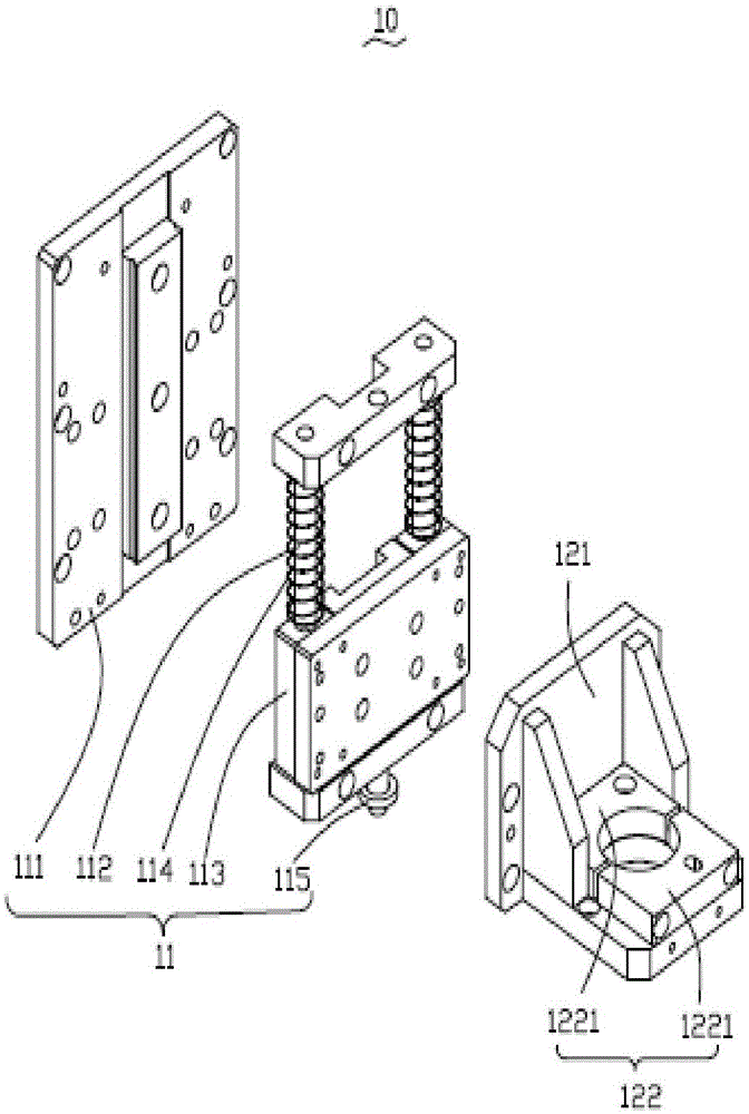
[0018] The automatic screw locking machine 100 includes a lifting assembly 10 , a locking assembly 20 , a guiding assembly 30 , an adsorption assembly 40 , a detection assembly 50 and a control module 60 . The locking assembly 20 , the guiding assembly 30 , the adsorption assembly 40 and the detection assembly 50 can be driven by the lifting assembly 10 to carry out lifting movement. The locking component 20 and the guiding component 30 can move relative to the adsorption component 40 under the action of extern...


PUM


Abstract

The invention provides an automatic screw locking machine which comprises a suction nozzle which is connected with a vacuum generator and used for adsorbing a screw. The suction nozzle comprises a body and an adsorbing end located at one end of the body; an air flow channel penetrating through the adsorbing end and the body is arranged in the suction nozzle, the adsorbing end comprises an end portion far away from the body, an inner side wall opposite to the air flow channel and a stop face arranged on the inner side wall. When the suction nozzle adsorbs the screw, the screw enters the adsorbing end from the end portion and is stopped by the stop face; the inner side wall is further provided with a flow guiding groove which is in a spiral shape, extends from the end portion to the stop face and penetrates through the stop face to be communicated with the air flow channel.

Description

technical field [0001] The invention relates to the field of automatic screw locking, in particular to an automatic screw locking machine. Background technique [0002] The vacuum suction type automatic locking screw machine usually includes a suction nozzle for absorbing screws and a screwdriver for locking screws. The end generates the suction force for the suction screw. The screwdriver passes through the suction nozzle to lock the screw absorbed by the suction end. But usually, because the size of the part of the suction end that accommodates the screw is slightly larger than the size of the screw, when the screw enters the suction end, it may be inclined relative to the inner wall of the adsorption end and be stuck between the inner wall of the adsorption end. When the screwdriver locks the screw There will be problems such as sliding teeth and floating locks, and the locking yield is low. Contents of the invention [0003] In view of the deficiencies in the above ...

Claims


Application Information

Patent Timeline
IPC IPC(8): B23P19/06
CPCB23P19/006B23P19/06
Inventor 史美珍
Owner 桐乡市建春塑业股份有限公司
Why Eureka
Try Eureka