
A cable fixing clip

A technology of fixing clips and wire tubes, applied in the direction of electrical components, etc., can solve the problems of deviation and offset in the installation position of the distribution box, and the holes of the distribution box cannot match the pre-embedded wire tubes, etc., so as to increase the utilization rate , The effect of reducing construction costs

Active Publication Date: 2019-11-12
CHINA MCC5 GROUP CORP
View PDF9 Cites 0 Cited by
  • Summary
  • Abstract
  • Description
  • Claims
  • Application Information

AI Technical Summary

Problems solved by technology

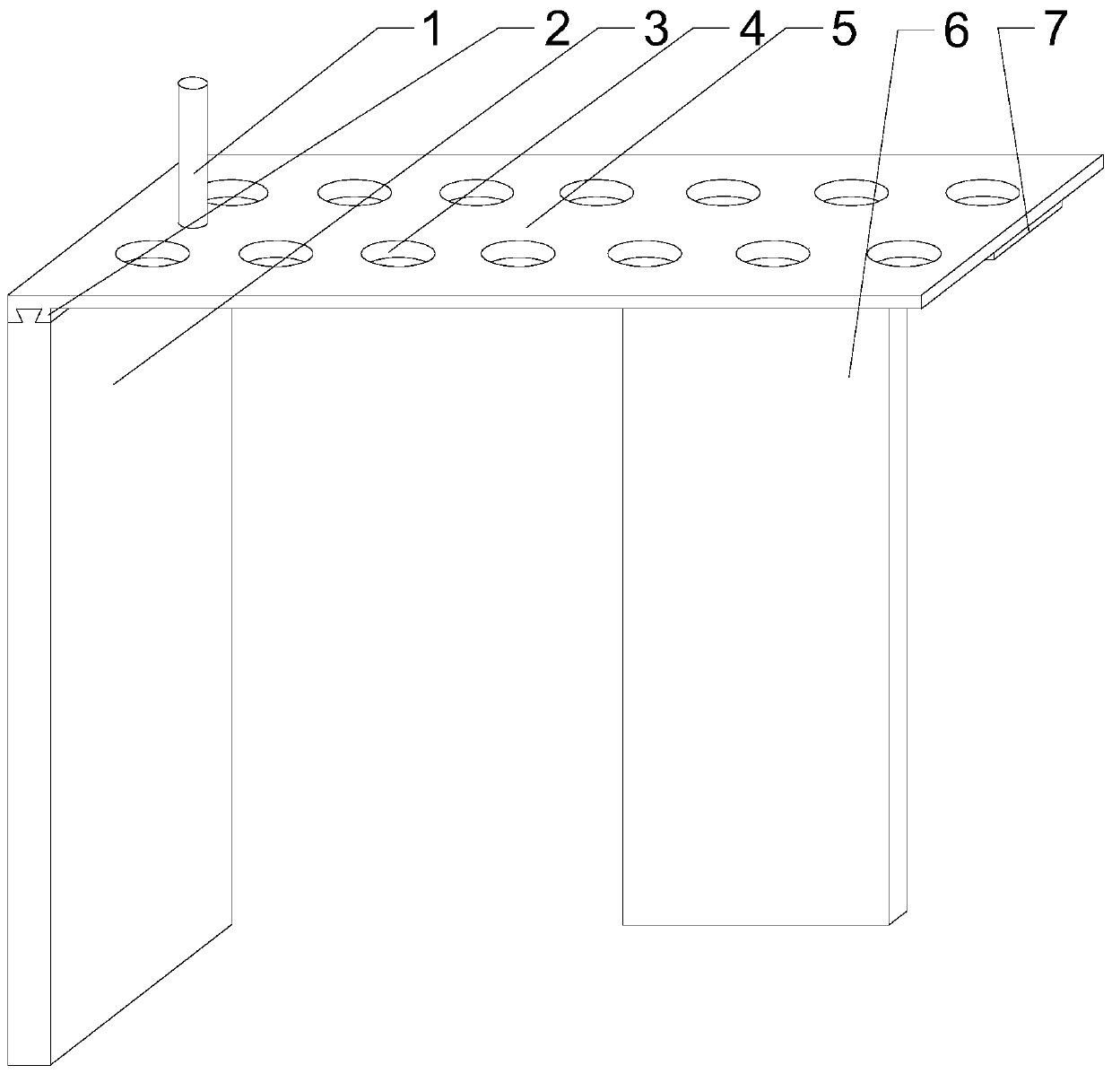
In view of the existing technology, after the pre-embedded line pipe is deployed, it is easy to shift during the later civil bricklaying process, which eventually leads to a deviation in the installation position of the distribution box, and the holes of the distribution box cannot match the pre-embedded line pipe Defects, the applicant designed a wire pipe fixing clip, that is to use the support plate, side plate and movable plate to construct a limit platform for temporarily fixing the exposed pre-embedded wire pipe part, thereby reducing the exposed during the later civil construction. The probability of deviation of the pre-embedded wire pipe to ensure that the hole in the distribution box and the pre-embedded wire pipe are kept in the center; when in use, first assemble the wooden limit platform, that is, place the support plate horizontally, and then place the side plate on the top Move the protrusions into the trapezoidal grooves to achieve partial support at the bottom of the support plate, then move the top of the movable plate into the chute, and since the chute and the trapezoidal grooves are perpendicular to each other, use the side plates and the movable plate to realize the alignment of the adjacent The support of the two sides of the support plate, the end of the pre-embedded wire tube is fixed after passing through the corresponding limit hole, and the final position of the movable plate is reasonably adjusted according to the specific number of pre-embedded wire tubes entering the distribution box. The remaining two sides of the limit platform are opened. During the later civil construction, when the concrete invades the parts of the pre-embedded pipes close to the ground, it will not cause the pre-embedded pipes to shift, ensuring that the pre-embedded pipes and the distribution box Hole Centering Efficiency

Method used


Image

  • A cable fixing clip
  • A cable fixing clip

Examples


Embodiment 1

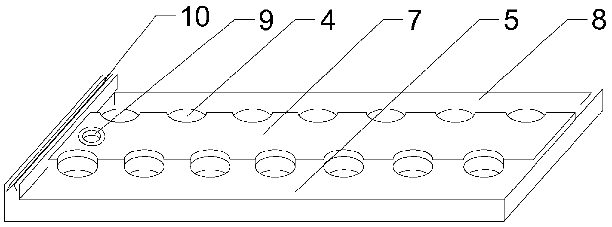
[0022] Such as Figure 1~2 As shown, the present embodiment includes a rectangular support plate 5 and a side plate 3, a plurality of limit holes 4 are opened on the support plate 5, and corrugated strips 2 are arranged on the lower surface of the support plate 5, and the corrugated strips 2 There is a trapezoidal groove 10 with a length equal to that of the corrugated strip 2, a protrusion matching the trapezoidal groove 10 is provided on the upper end surface of the side plate 3, and a vertical groove with the corrugated strip 2 is also provided on the lower surface of the supporting plate 5. chute 8, and both ends of the chute 8 are closed, the upper end of the movable plate 6 is slidingly arranged in the chute 8, and the support plate 5, the side plate 3 and the movable plate 6 constitute a limiting platform for fixing the pre-embedded pipe . In view of the existing technology, after the pre-embedded line pipe is deployed, it is easy to shift during the later civil brickl...

Embodiment 2

[0025] Such as Figure 1~2 As shown, in this embodiment, the plurality of limiting holes 4 are distributed into two groups along the long side of the support plate 5 , and the plurality of limiting holes 4 in the same group are distributed at equal intervals. The distribution of multiple holes on the distribution box is relatively uniform. In order to improve the centering efficiency between the pre-embedded wire pipe and the holes, the multiple limiting holes 4 on the support plate 5 are divided into two groups, and each group of limiting holes 4 is along the The long sides of the support plate 5 are evenly distributed to avoid excessive deformation when the pre-embedded wire tube passes through the limiting hole 4, and ensure that the cable enters the distribution box smoothly when the cable is deployed.

[0026] The present embodiment also includes a dividing plate 7 placed on the lower surface of the supporting plate 5, a screw hole is provided on the supporting plate 5, a...


PUM


Abstract

The invention discloses a wire tube fixing clamp which comprises a rectangular support plate and a side plate. The support plate has a plurality of stopping holes. A ridge is arranged on the lower surface of the support plate, and is provided with a trapezoidal groove having a length equal to that of the ridge. A protrusion in cooperation with the trapezoidal groove is disposed on the upper end surface of the side plate. A sliding groove perpendicular to the ridge is disposed on the lower surface of the support plate. The two ends of the sliding groove are closed. The upper end of a movable plate is slidably disposed in the sliding groove. The support plate, the side plate and the movable plate constitute a stopping platform for fixing a pre-embedded wire tube. The wire tube fixing clamp,by the support plate, the side plate and the movable plate, constructs the stopping platform for temporarily fixing the exposed pre-embedded wire tube, so as to reduce the deviation probability of theexposed pre-embedded wire tube in later civil construction to ensure that a distribution box hole is aligned with the pre-embedded wire tube.

Description

technical field [0001] The invention relates to the field of building construction, in particular to a line pipe fixing clip. Background technique [0002] Power distribution box is assembled in closed or semiclosed metal safe by electrical wiring requirement by switchgear, measuring instrument, protective device and auxiliary equipment or on screen width, forms low-voltage distribution equipment. During normal operation, the circuit can be connected or disconnected by means of a manual or automatic switch. Cut off the circuit or alarm with the help of protective electrical appliances in case of failure or abnormal operation. Various parameters in operation can be displayed by means of measuring instruments, and some electrical parameters can also be adjusted to prompt or send out signals for deviations from normal working conditions. Commonly used in various power generation, distribution and substations. During the construction of indoor wiring in buildings, due to the ...

Claims


Application Information

Patent Timeline
Patent Type & Authority Patents(China)
IPC IPC(8): H02G3/12H02G3/38
CPCH02G3/128H02G3/38
Inventor 郭东升范东岭李永帅
Owner CHINA MCC5 GROUP CORP
Learn More