A prefabricated reinforced concrete composite column

A technology of reinforced concrete and composite columns, applied in the direction of columns, pillars, pier columns, etc., can solve the problems of low efficiency in the assembly process and long time spent by workers, and achieve the effect of improving efficiency, improving efficiency, and reducing visual errors

Active Publication Date: 2022-06-17
福建九鼎建设集团有限公司 +2
View PDF0 Cites 0 Cited by
  • Summary
  • Abstract
  • Description
  • Claims
  • Application Information

AI Technical Summary

Problems solved by technology

[0004] However, the following problems exist in the entire assembly process: when aligning the assembly holes with the steel bars at the column head, the alignment is generally done manually, and workers spend a long time on assembly, resulting in low efficiency of the entire assembly process

Method used


Image

  • A prefabricated reinforced concrete composite column
  • A prefabricated reinforced concrete composite column
  • A prefabricated reinforced concrete composite column

Examples


Embodiment 1

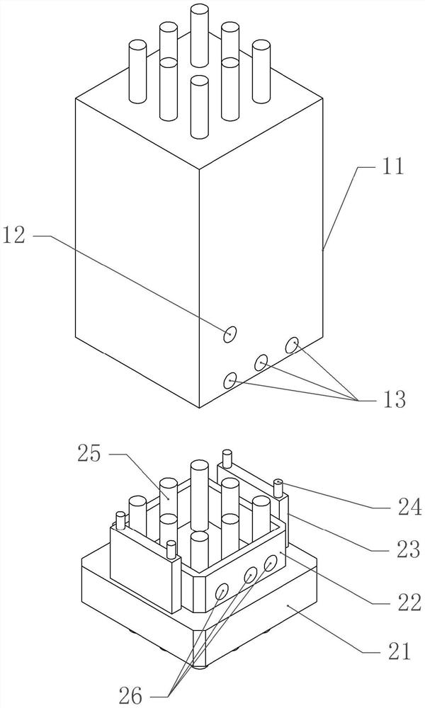
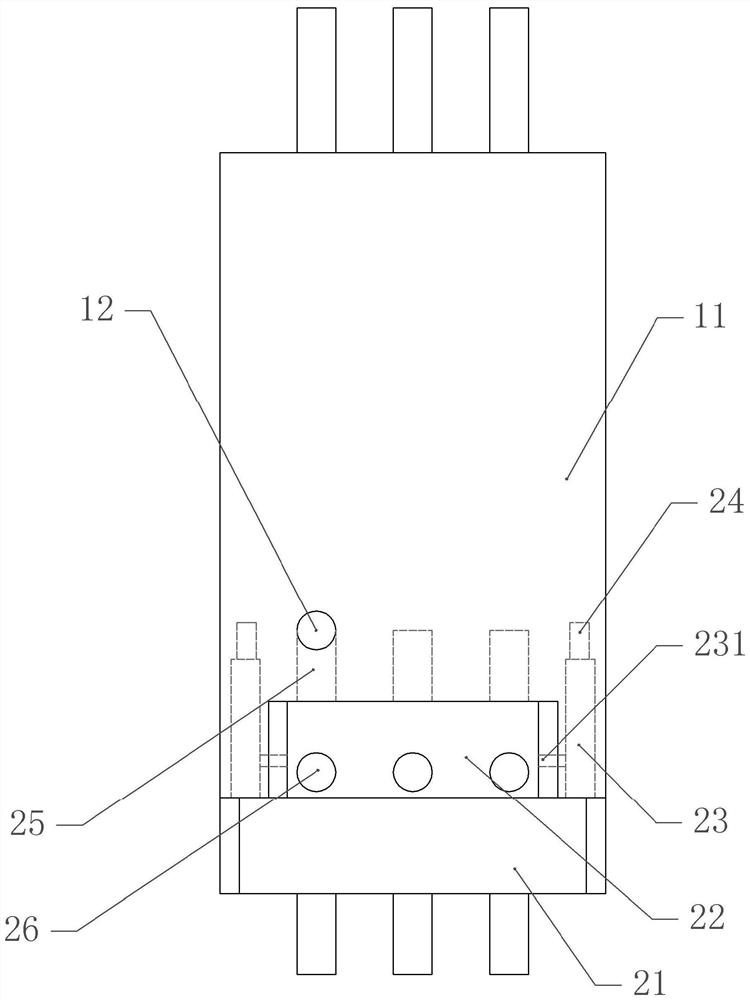
[0041] basically as attached figure 1 , attached figure 2 , attached image 3 and Figure 4 As shown, a prefabricated reinforced concrete composite column includes a prefabricated member 11 and an assembly part. The prefabricated member 11 includes a steel frame 14 composed of several steel bars. The steel frame 14 is rectangular. The first stirrups 15 are vertically evenly distributed. In this embodiment, the first stirrups 15 are closed stirrups. The outside and inside of the reinforcing bar frame 14 are filled with concrete, that is, prefabricated components are prefabricated.

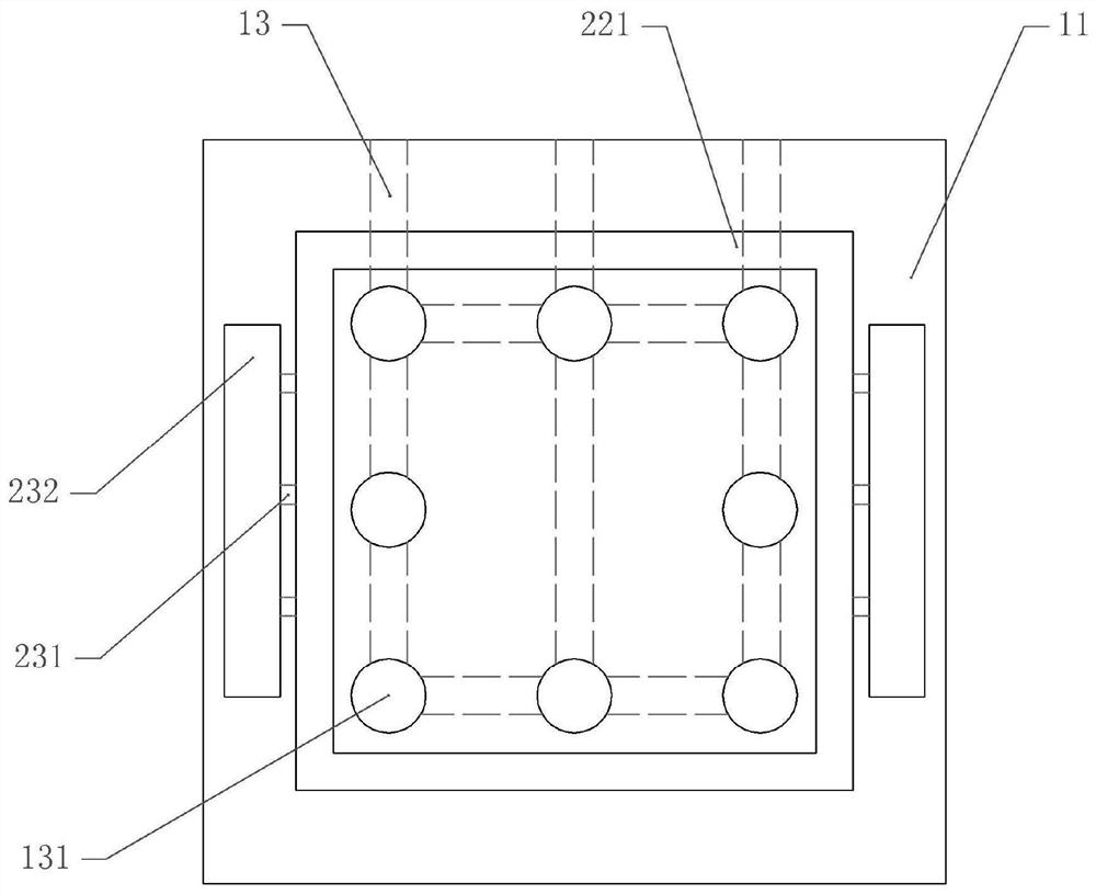
[0042] The bottom of the prefabricated member 11 is provided with a plurality of assembling holes 131 that are evenly distributed in a rectangular shape. The outer periphery of the assembling hole 131 is provided with a rectangular auxiliary positioning groove 221 , and positioning grooves 221 are formed on both sides of the auxiliary positioning groove 221 . In this embodiment, the prefabricate...

Embodiment 2

[0053] The difference between the second embodiment and the first embodiment is as follows: Figure 5 and attached Image 6 As shown, the reinforcing bar frame 14 is provided with a second stirrup 16. In this embodiment, the second stirrup 16 is improved. The second stirrup 16 includes a main stirrup 161 and an auxiliary stirrup 165. A T-shaped connecting portion 162 is integrally formed, and a T-shaped groove is formed on the auxiliary stirrup 165. The main stirrup 161 is assembled through the connecting portion 162 and the groove, so that the connecting portion 162 and the groove can slide relative to each other. , and also includes an elastic member. In this embodiment, the elastic member is a spring 164, one end of the spring 164 is welded on the auxiliary stirrup 165, the other end of the spring 164 is welded on the connecting portion 162, and a sleeve 163 is welded on the main stirrup 161. , the sleeve 163 is welded with the auxiliary stirrup 165 , that is, the sleeve 1...


PUM


Abstract

The invention relates to the technical field of reinforced concrete structures, and discloses an assembled reinforced concrete composite column, a prefabricated component and an assembly component, positioning grooves are arranged on both sides of the prefabricated component, and several assembly holes are arranged between the positioning grooves on both sides; The components include an assembly seat, and positioning plates are arranged on both sides of the assembly seat, and the positioning plates correspond to the positioning grooves one by one. There are a number of correction holes between the positioning plates on both sides. The positioning shaft is vertically slidably matched with the positioning plate. The invention has a simple structure, overcomes the problem of low efficiency of manual positioning with naked eyes during the assembly process of the prefabricated reinforced concrete composite column in the prior art, and performs multiple positionings to improve the assembly accuracy of the assembled reinforced concrete composite column .

Description

technical field [0001] The invention relates to the technical field of reinforced concrete structures, in particular to an assembled reinforced concrete composite column. Background technique [0002] The prefabricated monolithic reinforced concrete structure refers to the prefabricated part of the components prefabricated by the prefabrication factory or workshop, transported to the site for assembly, and then poured concrete on the assembled components to connect the prefabricated components into a whole reinforced concrete structure. [0003] In the prior art, the assembly method of the assembled reinforced concrete composite column is as follows: pre-adjust the column head steel bars at the assembly position, so that the spacing between adjacent steel bars is basically the same, and the column head steel bars are in a vertical state, and then use a tower crane or The crane transports the prefabricated reinforced concrete composite column to the assembly position. When th...

Claims


Application Information

Patent Timeline
Patent Type & Authority Patents(China)
IPC IPC(8): E04C3/34E04B1/21
CPCE04C3/34E04B1/21
Inventor 杨国黄晓锋缪颖汤昌环周福彬
Owner 福建九鼎建设集团有限公司
Why Eureka
Try Eureka