Lifting jack with lifting pre-tightening device and method for lifting jack for pre-tightening lifting steel strands

A steel strand and jack technology is applied in the field of prestressed auxiliary construction devices, which can solve the problems of cumbersome disassembly and installation work, lack of force, loss, etc., and achieve the effects of simple and feasible preloading method, improved safety, and simple structure.

Inactive Publication Date: 2015-12-16
LIUZHOU OVM MASCH CO LTD
View PDF6 Cites 2 Cited by
  • Summary
  • Abstract
  • Description
  • Claims
  • Application Information

AI Technical Summary

Problems solved by technology

[0002] During the lifting construction of large components, the lifting structure is generally complicated and bulky due to the heavy weight to be lifted. For this reason, the lifting jack needs to be lifted and lowered synchronously; during the repeated lifting and lowering process, due to the lifting clip There are many pieces, the clamping effect cannot be exactly the same, and the lifting clips will be worn to varying degrees after being used for a certain number of times, which will cause some steel strands to be less stressed or not when the weight is lifted to a certain height. Stress situation
In this case, the usual practice is to continue lifting as long as the reserve safety factor of the steel strands allows. If the lifting safety is affected, the steel strands need to be reinstalled. Such a project is quite huge
[0003] The patent publication number is CN1640805A, and the title of invention is "Pretensioning Method for Lifting Steel Strands in Continuous Lifting Jacks", which discloses a lifting jack with a pretensioning device. The upper clamping top; the pre-tightening method for the lifting steel strand in the continuous lifting jack needs to loosen the lifting clip on the upper clamping top and the lifting clip on the anchor plate. After pre-tightening the steel strand, it is necessary Reinstall the loosened pressure plate and the lifting clip on the anchor plate into the anchor plate on the upper clamping top of the lifting jack, and complete the anchoring of each steel strand; the disadvantage of this is: disassembly and installation work It is cumbersome, and it is inconvenient to store the pressing plate and lifting clip after disassembly, and it is easy to be scattered and lost, which affects the construction progress and construction quality

Method used


Image

  • Lifting jack with lifting pre-tightening device and method for lifting jack for pre-tightening lifting steel strands
  • Lifting jack with lifting pre-tightening device and method for lifting jack for pre-tightening lifting steel strands
  • Lifting jack with lifting pre-tightening device and method for lifting jack for pre-tightening lifting steel strands

Examples


Embodiment 1

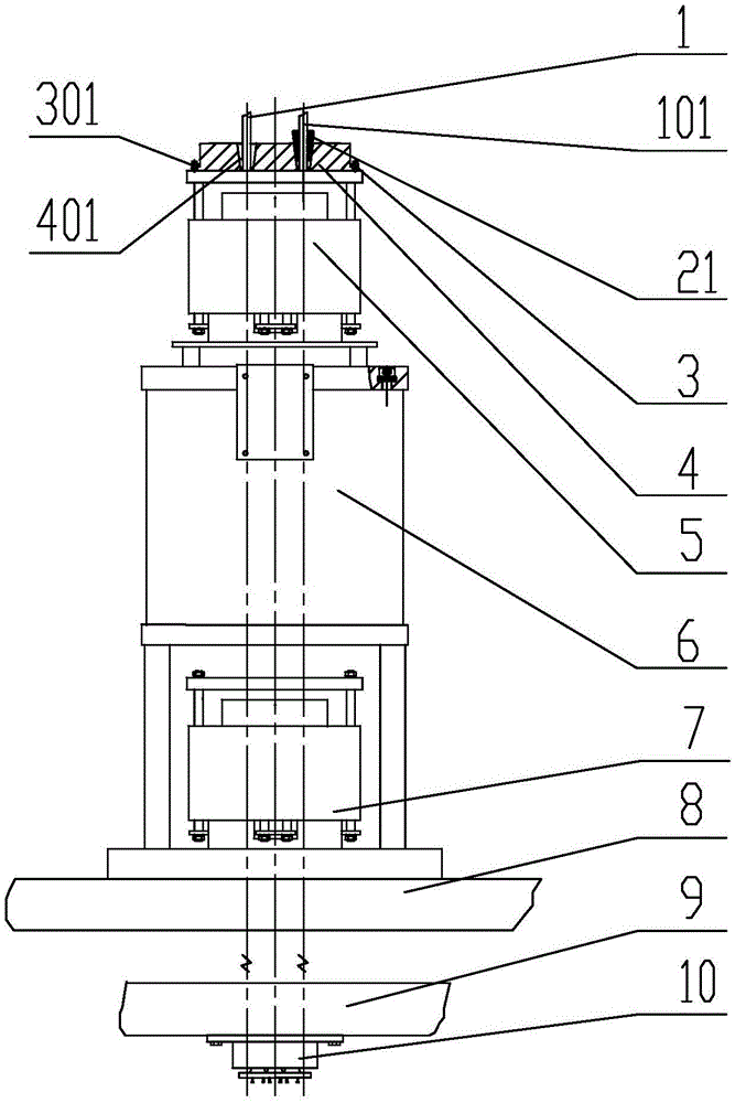
[0032] A lifting pretensioning device, the lifting pretensioning device is composed of an upper lifting clip 21, a pressure plate 3 and a pretensioning block 4 (see figure 1 ),

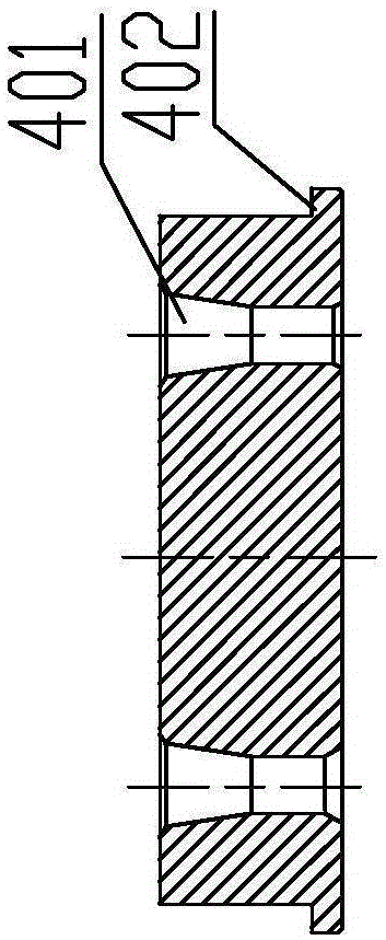
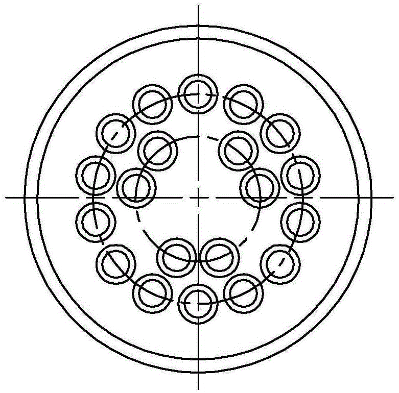
[0033] The pre-tightening block 4 is a short cylinder with a boss 402 at the bottom of the short cylinder, and there are n tapered holes 401 for installing the upper lifting clip 21 on the short cylinder, see diagram 2-1 , Figure 2-2 ;

[0034] The pressure plate 3 used to connect the pre-tightening block and the upper clamping top is circular, and there are m through holes 301 on the circular ring, and there is an inner step 302 in the circular ring; see Figure 3-1 , Figure 3-2 ;

[0035] In the working state, the pre-tightening block 4 is fixedly installed on the upper clamping top 5 of the main top 6, and the upper lifting clip 21 is placed in the taper hole 401 of the corresponding pre-tightening block 4 of the steel strand 101 to be adjusted; The annular pressure plate 3 is located outsi...

Embodiment 2

[0040] A lifting jack with a lifting pretensioning device.

[0041] Such as figure 1 As shown, the lifting jack of the lifting and pre-tensioning device includes an upper clamping top 5, a main top 6 and a lower clamping top 7 connected in sequence, and a lifting and pre-tensioning device.

[0042] The lifting pretensioning device is the lifting pretensioning device described in the first embodiment, which is composed of an upper lifting clip 21, a pressure plate 3 and a pretensioning block 4 (see figure 1 ),

[0043] In the working state, the pre-tightening block 4 is fixedly installed on the upper clamping top 5 of the main top 6, and the upper lifting clip 21 is placed in the taper hole 401 of the corresponding pre-tightening block 4 of the steel strand 101 to be adjusted; The annular pressure plate 3 is located outside the pretension block 4, the inner step 302 of the annular pressure plate 3 is stuck on the boss 402 of the pretension block 4, and the bolts and washers p...

Embodiment 3

[0045] A method for pre-tightening a steel strand, which uses the lifting jack with a lifting pre-tightening device described in Embodiment 2 to realize pre-tensioning of a certain steel strand during the process of synchronous lifting of heavy objects by the lifting jack. tight way.

[0046] When the lifting jack with the above-mentioned lifting pretensioning device is used to lift heavy objects, the connection method between the jack and the heavy object is the same as that of the ordinary lifting jack. The upper clamping top 5, main top 6 and The lower clamping top 7 is sequentially connected and installed on the load-bearing member, the pre-tension block 4 is fixedly installed on the upper clamping top 5 of the main top 6, and the upper lifting clip 21 is placed on the corresponding pre-tensioner of the steel strand 101 to be adjusted. In the taper hole 401 of the tight block 4; the annular pressure plate 3 is located outside the pre-tension block 4, and the bolts and washer...


PUM


Abstract

A lifting jack with a lifting pre-tightening device comprises an upper clamping jack body, a main jack body, a lower clamping jack body and the lifting pre-tightening device which are sequentially connected. The lifting pre-tightening device is composed of upper lifting clamping sheets, a pressing plate and a pre-tightening block. The pre-tightening block is a short cylinder with a boss at the bottom, and n conical holes used for mounting of the upper lifting clamping sheets are formed in the short cylinder. The pressing plate is in the shape of a circular ring, m through holes are formed in the circular ring, and an inner step is arranged in the circular ring. In the work state, the pre-tightening block is fixedly arranged on the upper clamping jack body of the main jack body, and the upper lifting clamping sheets are arranged in the conical holes, corresponding to the steel strands needing to be adjusted, of the pre-tightening block; and the pressing plate is located outside the pre-tightening block, the inner step of the pressing plate is clamped on the boss of the pre-tightening block, and bolts and gaskets penetrate the through holes in the outer surface of the pressing plate, so that the pressing plate, the pre-tightening block and the upper clamping jack body are connected. According to the lifting jack with the lifting pre-tightening device, in the lifting process, the problematic steel strands can be evenly pre-tightened in time, m is an integer from 2 to 20, and n is an integer from 7 to 66.

Description

technical field [0001] The invention relates to a prestress auxiliary construction device, in particular to a lifting jack with a lifting pretensioning device and a method for pretensioning a lifting steel strand. Background technique [0002] During the lifting construction of large components, the lifting structure is generally complicated and bulky due to the heavy weight to be lifted. For this reason, the lifting jack needs to be lifted and lowered synchronously; during the repeated lifting and lowering process, due to the lifting clip There are many pieces, the clamping effect cannot be exactly the same, and the lifting clips will be worn to varying degrees after being used for a certain number of times, which will cause some steel strands to be less stressed or not when the weight is lifted to a certain height. Stress situation. In this case, the usual practice is to continue to lift as long as the reserve safety factor of the steel strand allows. If the lifting safet...

Claims


Application Information

Patent Timeline
Patent Type & Authority Applications(China)
IPC IPC(8): B66F3/25B66F3/30
Inventor 梁涛严李荣庞俊辉王维刚卢卫平刘俊
Owner LIUZHOU OVM MASCH CO LTD
Why Eureka
Try Eureka