Interface modification method of SiCf/SiC composite material
A composite material and modification technology, which is applied in the field of interface modification of SiCf/SiC composite materials, can solve problems such as strong interface bonding and adverse effects on material properties, and achieve improved interface bonding, shortening the preparation cycle, and improving bending strength and fracture The effect of toughness
- Summary
- Abstract
- Description
- Claims
- Application Information
AI Technical Summary
Problems solved by technology
Method used
Image

Examples
Embodiment 1
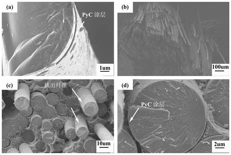
[0037] (2) SiC obtained in step (1) f / PyC intermediate placed in LPVCS (liquid polycarbosilane containing vinyl) impregnation solution, vacuum impregnated for 24h. Take out the vacuum-impregnated intermediate and put it into a graphite mold, and carry out cross-linking molding under a flowing nitrogen atmosphere: at a heating rate of 2°C·min -1 , first raise the temperature to 180°C, keep it warm for 1h, then continue to raise the temperature to the crosslinking temperature of 250°C at the same heating rate, keep it warm for 1h, and the nitrogen flow rate is 100L h -1 . Take out the cross-linked intermediate and put it into a cracking furnace, and crack it in a flowing nitrogen atmosphere at a high temperature. The cracking temperature is 1100°C, and the heating rate is 8°C·min. -1 , the flow rate of nitrogen gas is 3L·h -1 . A total of 9 processes of vacuum impregnation-cross-linking molding-pyrolysis were carried out. Among them, the cross-linking molding process of the...
Embodiment 2
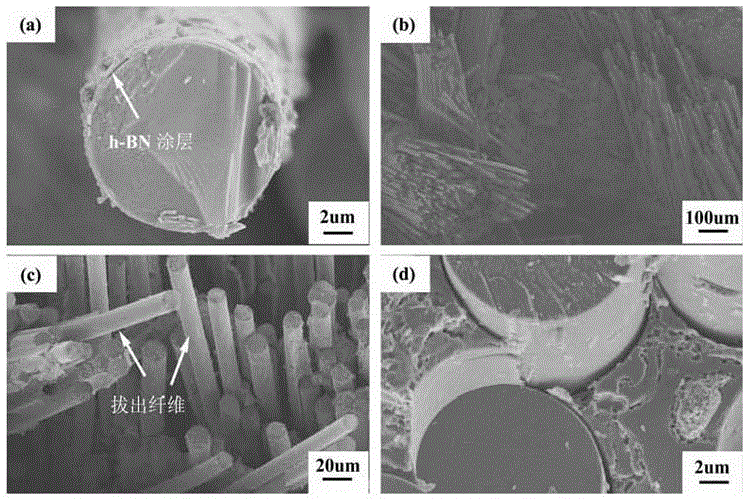
[0044] (2) SiC in step (1) f / h-BN intermediate placed in LPVCS impregnation solution, vacuum impregnation for 6h. Take out the vacuum-impregnated intermediate and put it into a graphite mold, and carry out cross-linking molding under a flowing nitrogen atmosphere: at a heating rate of 3°C·min -1 , first raise the temperature to 200°C, keep it warm for 0.5h, then continue to raise the temperature to the crosslinking temperature of 350°C at the same heating rate, keep it warm for 1.5h, and the nitrogen flow rate is 150L h -1 . Take out the cross-linked intermediate and put it into a cracking furnace, and crack it in a flowing nitrogen atmosphere at a high temperature. The cracking temperature is 1100°C, and the heating rate is 8°C·min. -1 , the nitrogen flow rate is 1L·h -1 . A total of 10 vacuum impregnation-cross-linking molding-pyrolysis processes were carried out. Among them, the cross-linking molding process of the first process cycle was assisted by hot molding, and t...
Embodiment 3
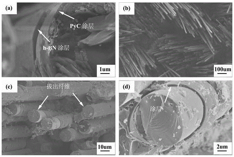
[0051] (2) SiC obtained in step (1) by LPCVD process f / PyC intermediate surface to prepare h-BN coating, the specific steps are: using boron trichloride and ammonia as source gas, nitrogen and hydrogen as dilution gas, SiC f The / PyC intermediate is placed in a CVD deposition furnace, and the chemical vapor deposition is carried out by the differential pressure method. The deposition temperature is 900 ° C, the deposition time is 1 h, the deposition pressure is 1500 Pa, and the flow rate of boron trichloride is 1 L h -1 , the flow rate of ammonia gas is 3L·h -1 , the flow rate of hydrogen is 10L·h -1 , the nitrogen flow rate is 10L·h -1 , to obtain a fiber preform with PyC coating / h-BN coating, that is, SiC f / (PyC / h-BN) intermediate.
[0052] (3) SiC obtained in step (2) f / (PyC / h-BN) intermediate was placed in LPVCS impregnation solution and vacuum impregnated for 12h. Take out the vacuum-impregnated intermediate and put it into a graphite mold, and carry out cross-li...
PUM
| Property | Measurement | Unit |
|---|---|---|
| density | aaaaa | aaaaa |
| bending strength | aaaaa | aaaaa |
| density | aaaaa | aaaaa |
Abstract
Description
Claims
Application Information
PatSnap Eureka turns technology decisions into work you can execute. Powered by our Innovation Knowledge Graph, it runs expert workflows across engineering, life sciences, materials and intellectual property. Get your review-ready output in minutes.


