Small box girder bridge and building method thereof

A small box girder and bridge technology, applied in bridge construction, bridges, erection/assembly of bridges, etc., can solve problems such as time-consuming, achieve high continuity, improve use efficiency, and improve construction quality.

Inactive Publication Date: 2015-12-16
CHINA RAILWAY SIYUAN SURVEY & DESIGN GRP
View PDF6 Cites 7 Cited by
  • Summary
  • Abstract
  • Description
  • Claims
  • Application Information

AI Technical Summary

Problems solved by technology

[0005] The purpose of the embodiments of the present invention is to provide a small box girder bridge and its construction method to solve the time-consuming problem of the prior art

Method used


Image

  • Small box girder bridge and building method thereof
  • Small box girder bridge and building method thereof

Examples


Embodiment 1

[0024] Embodiment 1 provided by the present invention is an embodiment of a kind of small box girder bridge provided by the present invention, in the embodiment of a kind of small box girder bridge provided by the present invention:

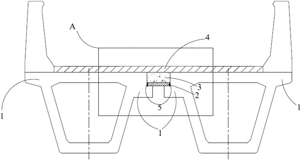
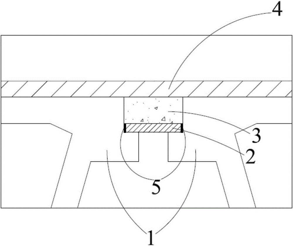
[0025] Such as figure 1 Shown is the structural representation of the embodiment of the closed structure of two transversely connected small box girders in a kind of small box girder bridge provided by the present invention, as figure 2 Shown is provided by the present invention figure 1 The partial enlarged view of part A in the middle is represented by figure 1 and figure 2 It can be seen that in this closed structure:

[0026] The width and depth of the groove can be adjusted according to the actual structure and operating environment of the small box girder, the width can range from 300-1000mm, and the depth can range from 15-25mm. The cross section of the groove can be trapezoidal, U-shaped or rectangular. figure 1 and figure 2 In t...

Embodiment 2

[0034] Embodiment 2 provided by the present invention is an embodiment of a construction method of a small box girder bridge provided by the present invention, and an embodiment of a construction method of a small box girder bridge provided by the present invention includes the following steps:

[0035] Step 1, make and install the small box girder;

[0036] The upper edge of the flange plate at the transverse connection between the manufactured small box girder and another small box girder is provided with a concave angle formed by inward depression; when placed, the two concave angles at the joint of two horizontally connected small box girders combined to form a groove with an upward opening direction;

[0037] Step 2, place a prefabricated plate whose size matches the size of the groove on the bottom surface of the groove;

[0038] Step 3, filling the sealing filler in the gap between the prefabricated panel and the flange panel;

[0039] Step 4, perform cast-in-place we...


PUM


Abstract

The invention belongs to the field of bridge structural engineering and provides a small box girder bridge and a building method thereof. The small box girder bridge comprises at least two small box girders which are transversely connected. The joint of flange plates of every two transversely-connected small box girders is provided with a groove with an upward opening. Due to the fact that each groove is formed in the joint of the two corresponding small box girders and steel plates or concrete plates or composite material plates serving as bottom molds of cast-in-place wet joints are placed in the grooves, leakage and falling objects can be effectively prevented, potential safety hazards to the position below the bridge are reduced and even eradicated, and safety of construction above an electrified railway, a road or a building is guaranteed; wet joint construction is performed in the grooves, the wet joints will be connected with a prefabricated plate after being formed in a poured manner, the bending rigidity of the wet joints is greatly improved, and meanwhile, the transverse integrity of the bridge is enhanced to a certain extent; and continuity is high in the on-site transverse connecting construction work process of the small box girders, construction quality is improved, and the blocking and controlling time of trains and roads is greatly shortened.

Description

technical field [0001] The invention belongs to the field of bridge structure engineering, in particular to a small box girder bridge and a construction method thereof. Background technique [0002] Box girder is a box-shaped girder structure in bridge engineering. Small box girders are more convenient to erect because of their better bridge structure. At present, when bridges with small and medium spans span existing railways and highways Most of them adopt the form of split combined small box girders. [0003] When doing small box girder bridge construction work on electrified railway lines, roads or structures, such as pouring wet joints, etc., there may be concrete slurry, aggregates and even formwork related parts falling under the bridge. , leading to major traffic accidents, the safety risk is huge, so the construction of small box girder bridges requires protective measures. The protection method in the prior art is generally to set up a protective scaffolding, and ...

Claims


Application Information

Patent Timeline
Patent Type & Authority Applications(China)
IPC IPC(8): E01D2/04E01D21/00
Inventor 林峰
Owner CHINA RAILWAY SIYUAN SURVEY & DESIGN GRP
Why Eureka
Try Eureka