Throwing lever anti-collision device, throwing lever assembly and anti-collision gate

An anti-collision device and gate lever technology, applied in the field of barrier gates, can solve the problems of reducing the degree of automatic operation of barrier gates, inconvenient use, etc., and achieve the effect of convenient use and anti-collision damage

Active Publication Date: 2015-12-16
JIANGXI BAISHENG GATE & DOOR AUTOMATION
View PDF8 Cites 11 Cited by
  • Summary
  • Abstract
  • Description
  • Claims
  • Application Information

AI Technical Summary

Problems solved by technology

[0004] However, after the pushing force of the above-mentioned anti-collision barrier gate disappears, the operator needs to push the brake lever back to its original position and re-clamp it between the two clamping blocks.
Due to the need for manual operation, the degree of automatic operation of the barrier gate is reduced, and it is inconvenient to use

Method used


Image

  • Throwing lever anti-collision device, throwing lever assembly and anti-collision gate
  • Throwing lever anti-collision device, throwing lever assembly and anti-collision gate
  • Throwing lever anti-collision device, throwing lever assembly and anti-collision gate

Examples


Embodiment 1

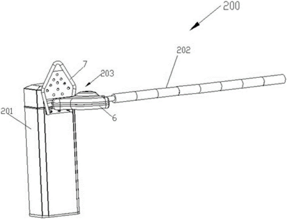
[0027] Such as figure 1 As shown, the anti-collision barrier barrier 200 includes a barrier barrier chassis 201, a control unit, a drive unit and a brake lever assembly. Both the control unit and the drive unit are installed on the barrier gate chassis 201 . The drive unit protrudes a rotatable main shaft from the barrier gate housing 201 . The brake lever assembly includes a brake lever 202 and a brake lever anti-collision device 203 .

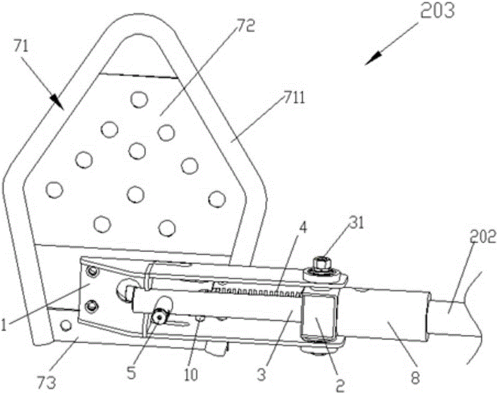
[0028] Such as figure 1 and 2 As shown, the brake lever anti-collision device 203 includes a chuck 1 , a clamp block 2 , a swing shaft 3 , a spring 4 , a spring mounting part, a position sensing part, a buffer 5 , a case 6 , a guide frame 7 and a guide post 8 .

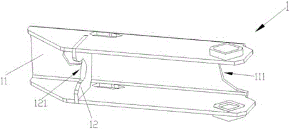
[0029] Such as image 3 As shown, the chuck 1 includes a chuck body 11 , a seat plate 12 and a chuck seat. The chuck main body 11 is a shell structure with three sides open. The rear side wall of the chuck main body 11 is fixedly connected to the main shaft through the chuck s...

Embodiment 2

[0045] In Embodiment 2, the brake lever anti-collision device has the same structure as Embodiment 1, and also includes two clamping units 13 . The structures in the second embodiment that are the same as those in the first embodiment are assigned the same numbers, and descriptions thereof are omitted.

[0046] Such as Figure 8 As shown, each clamping unit 13 includes an elastic steel sheet 131 and a nylon block 132 . Two elastic steel sheets 131 are symmetrically installed on the upper surface and the lower surface of the limit block 91 , and the nylon block 132 is connected to the front side of the elastic steel sheet 131 and leans against the surface of the balance shaft 3 . The distance between the nylon blocks 132 on the upper and lower sides is slightly smaller than the diameter of the pendulum shaft 3, so that the pendulum shaft 3 is clamped. When the vehicle hits the brake lever 202 forward, the pendulum shaft 3 squeezes the nylon block 132 to the front side, and th...


PUM


Abstract

The invention relates to a throwing lever anti-collision device, and belongs to the technical field of gates. The throwing lever anti-collision device comprises a chuck, a clamping block, a spring, a balance shaft, a position sensor and a guiding frame. The hollow chuck with an opening in the side wall is connected with a main shaft of a gate. The clamping block is contained in the chuck and connected to one side of the chuck in a pivoted manner. One end of the spring used for pushing the clamping block to rotate is connected to the clamping block in a pivoted manner, and the other end of the spring is connected with the chuck in a pivoted manner. The balance shaft is fixedly installed on the clamping block, one end of the balance shaft abuts against or is far away from one side of the chuck, and the other end of the balance shaft is connected with a throwing lever after extending out of the other side of the chuck. The position sensor is connected with a control unit of the gate and used for detecting the rotation position of the balance shaft. The guiding frame is installed on a gate crate and provided with an inclined rail used for supporting and guiding the throwing lever to move upwards. Compared with the prior art, the throwing lever anti-collision device has the following beneficial effects that the throwing lever can be prevented from being crashed, and the throwing lever can automatically reset after avoiding vehicles.

Description

technical field [0001] The invention relates to a brake rod anti-collision device, which belongs to the technical field of barrier gates. Background technique [0002] In the currently commonly used barrier gates, the gate lever is fixedly installed on the main shaft protruding from the chassis. The brake lever rotates around the main shaft, which can realize the release or blocking of the vehicle. When a vehicle forcibly bumps into the brake lever lowered by the barrier gate, it will cause damage to the brake lever. In order to solve the problem that the brake lever is easily damaged, anti-collision barriers have been developed. [0003] The existing anti-collision barrier has a chuck connected to the main shaft and a brake lever pivotally connected to the chuck. Two elastic clamping blocks are fixed on the chuck and the brake lever is clamped between the two. When the brake rod is not impacted, the relative position of the brake rod and the chuck remains unchanged, and ...

Claims


Application Information

Patent Timeline
Patent Type & Authority Applications(China)
IPC IPC(8): E01F13/06
Inventor 刘润根
Owner JIANGXI BAISHENG GATE & DOOR AUTOMATION
Why Eureka
Try Eureka